


Closed Loop Speed Mode
94 AX1500 Motor Controller User’s Manual Version 1.9b. June 1, 2007
Detailed information on how to install and wire optical encoders is provided at “Installing,
Connecting and Using the Encoder Module” on page 67.
If using optical encoders, omit the Analog Tachometer discussion in this section and
resume reading from “Control Loop Description” on page 96. Optical Encoders require
special handling. See “Installing, Connecting and Using the Encoder Module” on page 67
for a detailed discussion.
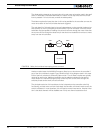
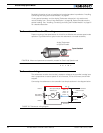
Tachometer or Encoder Mounting
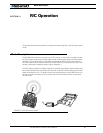
Proper mounting of the speed sensor is critical for an effective and accurate speed mode
operation. Figure 56 shows a typical motor and tachometer or encoder assembly.
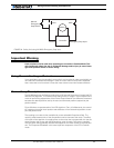
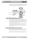
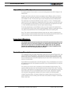
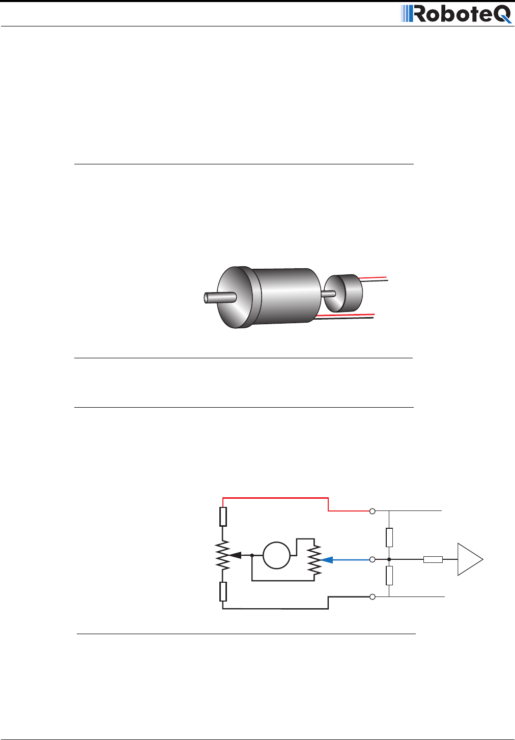
Tachometer wiring
The tachometer must be wired so that it creates a voltage at the controller’s analog input
that is proportional to rotation speed: 0V at full reverse, +5V at full forward, and 0 when
stopped.
Connecting the tachometer to the controller is as simple as shown in the diagram below.
P iti F db k
FIGURE 56. Motor and speed sensor assembly needed for Close Loop Speed mode
Speed feedbackSpeed feedback
Analog Tachometer
or Optical Encoder
47kOhm
10kOhm
47kOhm
1kOhm
Max Speed Adjust
10kOhm pot
Zero Adjust
100 Ohm pot
1kOhm
Internal Resistors
and Converter
+5V 14
Ground 5
A/D
Ta c h
Ana 1: 11
Ana 2: 10
Ana 3: 12
Ana 4: 8
FIGURE 57. Tachometer wiring diagram