


Closed Loop Position Mode
82 AX1500 Motor Controller User’s Manual Version 1.9b. June 1, 2007
Position Sensor Selection
The AX1500 may be used with the following kind of sensors:
• Potentiometers
• Hall effect angular sensors
• Optical Encoders (with Encoder Module)
The first two are used to generate an analog voltage ranging from 0V to 5V depending on
their position. They will report an absolute position information at all times.
Optical encoders report incremental changes from a reference which is their initial position
when the controller is powered up or reset. Using Optical Encoders in this mode is possi-
ble but requires special handling that is described in Figure , “Using the Encoder to Track
Position,” on page 77.
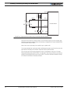
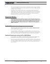
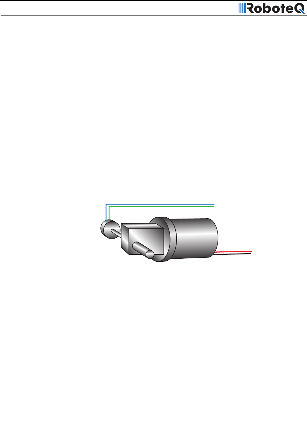
Sensor Mounting
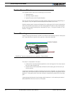
Proper mounting of the sensor is critical for an effective and accurate position mode opera-
tion. Figure 48 shows a typical motor, gear box, and sensor assembly.
The sensor is composed of two parts:
• a body which must be physically attached to a non-moving part of the motor assem-
bly or the robot chassis, and
• an axle which must be physically connected to the rotating part of the motor you
wish to position.
A gear box is necessary to greatly increase the torque of the assembly. It is also necessary
to slow down the motion so that the controller has the time to perform the position control
algorithm. If the gearing ratio is too high, however, the positioning mode will be very slug-
gish.
A good ratio should be such that the output shaft rotates at 1 to 10 rotations per second
(60 to 600 RPM) when the motor is at full speed.
Position Sensor
Gear box
Position Feedback
FIGURE 48. Typical motor/potentiometer assembly in Position Mode