


Analog Control and Operation
116 AX1500 Motor Controller User’s Manual Version 1.9b. June 1, 2007
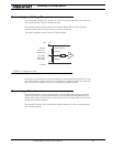
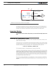
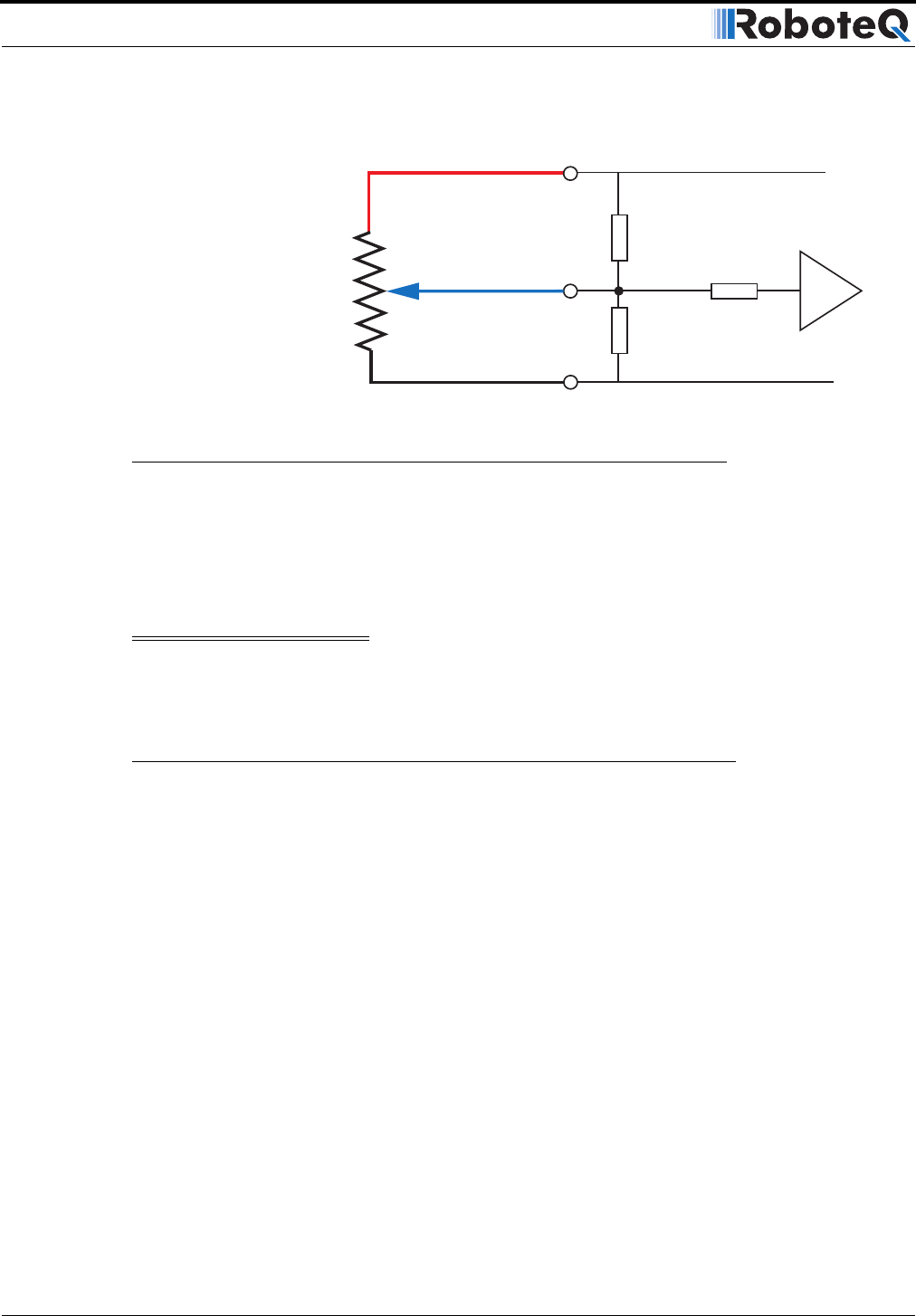
The controller includes two 47K ohm resistors pulling the input to a mid-voltage point of
2.5V. When configured in the Analog Input mode, this will cause the motors to be at the
Off state if the controller is powered with nothing connected to its analog inputs.
Important Notice
The controller will not activate after power up or reset until the analog inputs are at
2.5V
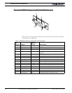
Selecting the Potentiometer Value
The potentiometer can be of almost any value. Undesirable effects occur, however, if the
value is too low or too high.
If the value is low, an unnecessarily high and potentially damaging current will flow through
the potentiometer. The amount of current is computed as the voltage divided by the poten-
tiometer’s resistance at its two extremes. For a 1K potentiometer, the current is:
I = U/R = 5V / 1000 Ohms = 0.005A = 5mA
For all practical purposes, a 1K potentiometer is a good minimal value.
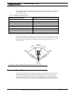
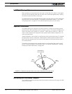
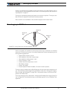
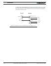
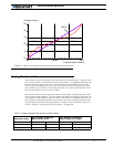
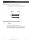
If the value of the potentiometer is high, then the two 47K resistors built into the controller
will distort the reading. The effect is minimal on a 10K potentiometer but is significant on a
100K or higher potentiometer. Figure 77 shows how the output voltage varies at the vari-
ous potentiometer positions for three typical potentiometer values. Note that the effect is
an exponentiation that will cause the motors to start moving slowly and accelerate faster
as the potentiometer reaches either end.
This curve is actually preferable for most applications. It can be corrected or amplified by
changing the controller’s exponentiation parameters (see “Command Control Curves” on
page 46.
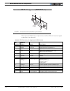
47kOhm
10kOhm
47kOhm
10kOhm
Internal Resistors
and Converter
Analog
Input 1
2
3
or 4
+5V
14
10
11
12
8
13
Ground
A/D
FIGURE 76. Potentiometer connection wiring diagram