Chapter 1 Sun Fire X2250 Server Overview 1-5
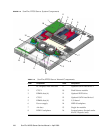
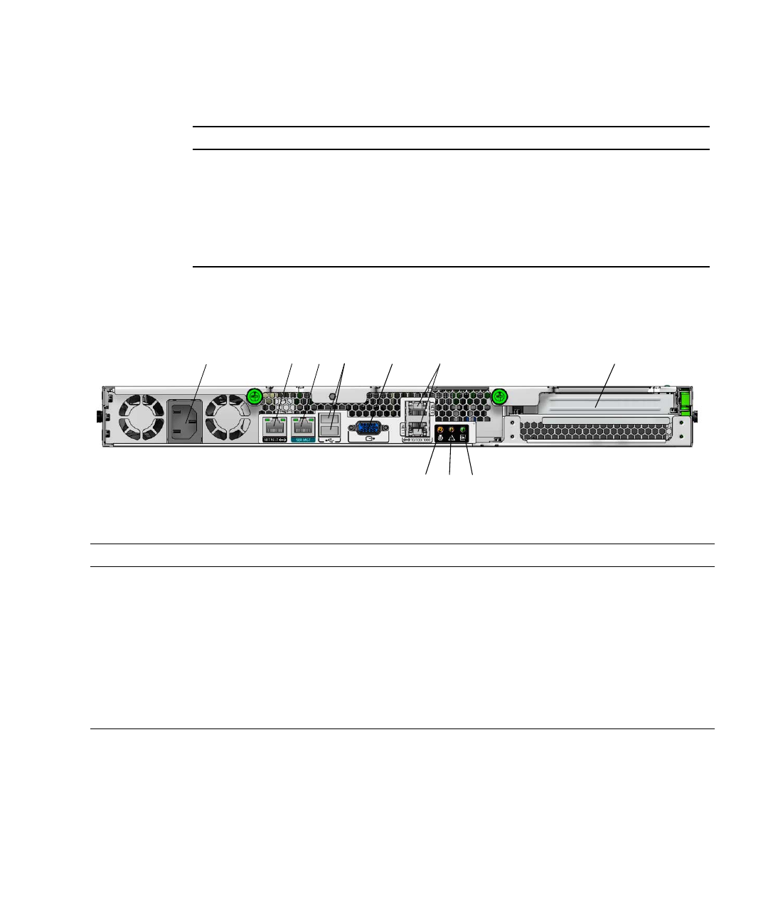
FIGURE 1-2 shows the back panel of the Sun Fire X2250 server.
FIGURE 1-2 Back Panel
1.3.2 Internal Components
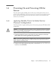
FIGURE 1-3 shows the locations of the components inside the Sun Fire X2250 server.
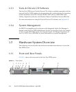
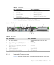
TABLE 1-2 Front Panel
Label Button/LED/Port Label Button/LED/Port
1 Locate LED/Switch 6 System serial label
2 Fault LED 7 USB 2.0 connectors (2)
3 Power/OK LED 8 Optional DVD drive
4 Power button 9 Optional SATA hard disk drive 1
5 Optional SATA hard disk drive 0
TABLE 1-3 Back Panel
Label Connector/Slot Label Connector/Slot
1 AC Power connector 6 Gigabit Ethernet ports (LAN-0 top, LAN-1
bottom)
2 Network Management (NET MGT) Ethernet
port
7 Locate LED
3 Serial Management (SER MGT) / RS-232-F
RJ-45 serial port
8 Fault LED
4 USB 2.0 connectors (2) 9 Power/OK LED
5 On-board HD15 video connector 10 PCI Express slot
2
10
9
6
34 5
7
8
1


