4-6 Sun Fire X2250 Server Service Manual • April 2009
4.5 Component Replacement Procedures
The following components are customer-replaceable units (CRUs):
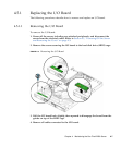
■ I/O board (see Section 4.5.1, “Replacing the I/O Board” on page 4-7)
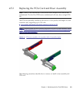
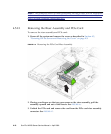
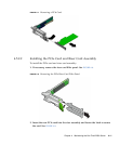
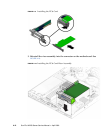
■ PCIe cards and risers (see Section 4.5.2, “Replacing the PCIe Card and Riser
Assembly” on page 4-9)
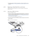
■ Hard disk drives and carriers (see Section 4.5.3, “Replacing a Hard Disk Drive and
Carrier” on page 4-13)
■ Hard disk drive backplanes (see Section 4.5.4, “Replacing an HDD Backplane
Assembly” on page 4-15)
■ Optical Disk Drive (DVD or CD) drive (see Section 4.5.5, “Removing and
Installing the ODD Drive Assembly” on page 4-18)
■ Air duct (see Section 4.5.6, “Replacing the Air Duct” on page 4-20)
■ Power supply (see Section 4.5.7, “Replacing the Power Supply” on page 4-22)
■ Single fan module (see Section 4.5.8, “Replacing the Single Fan Module” on
page 4-25)
■ Dual blower modules (see Section 4.5.9, “Replacing the Dual Blower Module” on
page 4-26)
■ Memory modules (DIMMs) (see Section 4.5.10, “Replacing Memory Modules” on
page 4-28)
■ Battery (see Section 4.5.11, “Replacing the System Battery” on page 4-33)
■ CPU - new installation (see Section 4.5.13, “Installing a New CPU” on page 4-41).
■ Cable kit (see Section 4.5.14, “Replacing Cables” on page 4-45)
The following component should be replaced only by trained field service
technicians:
■ CPU - replacement (see Section 4.5.12, “Replacing a CPU and Heatsink” on
page 4-36).
■ Motherboard (see Section 4.5.15, “.Motherboard” on page 4-46)
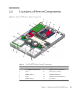
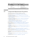
6 Power supply 14 HDD 0 backplane
7 Air duct 15 Single fan module
8 HDD 1 backplane 16 System battery (located under
the PCI Express card)
TABLE 4-1 Sun Fire X2250 Server Internal Components (Continued)
Label Component Label Component


