


2-72 Service Manual
Service checks
Anytime the system board is replaced, the Configuration ID must be reset in NVRAM. Go to “Configuration ID”
on page 3-21.
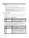
Review the following information before performing any service checks.
• Paper feed problems (especially paper jams): Go to “Display Log” on page 3-23 and check the printer
event log for indications of repetitive entries that help to isolate a problem to a particular area of the printer
or option.
• Paper feed problems with error message: Use the “Sub error codes for 9xx and 2xx error codes” on
page 2-8 to help diagnose the problem.
• Print quality problems: Go to “Print quality pages (Prt Quality Pgs)” on page 3-6 and print a test page to
help diagnose problems before changing any settings or working on the printer.
• Use the resident diagnostics test provided to help isolate a problem before taking the machine apart or
removing any options.
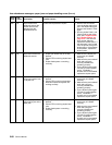
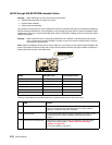
5-Bin mailbox service check
Service tip: The majority of the mechanical components can be observed during operation by removing the left
and right side covers.
Make sure the option(s) are correctly installed and the machine is configured correctly before attempting to
service the unit.
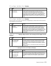
Problems with excessive static electricity buildup
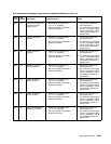
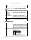
The printer does not recognize one or more output options as installed
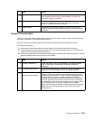
Service tip: If more than a single output option is installed, check each one to see if the printer recognizes any
single option as being installed. If the printer recognizes any of the output options then the base printer
autoconnect system is operating correctly and the problem is in the unrecognized option. Continue with this
service check or go to the service check for the failing output option.
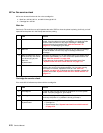
FRU Action
1 Front cover assembly Check the front cover assembly to make sure the ESD brush ground
lead is firmly attached to the 5-Bin mailbox frame. Also check to
make sure the ESD brush is not loose or damaged.
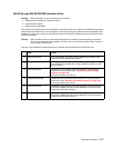
FRU Action
1 5-Bin mailbox option Check the autoconnects, cables, and connectors of the option for any
signs of loose or damaged parts.
2
Mechanical linkage
assembly
Remove the left and right side covers and check the two
autoconnects for damage, especially the connector pins. Remove the
output option and check the voltages on the standard output bin
autoconnect located on the top left rear of the printer. Go to
“Autoconnect” on page 5-6. If the voltages are correct, reinstall the
output option noting the position of the toroid on the autoconnect
cable of the lower autoconnect. Check the voltages on each of the
autoconnects. If the toroid was moved, make sure to move it back to
its original position on the cable. If the voltages are correct, replace
the control board. If the voltages are incorrect, replace the failing
autoconnect assembly.