


2-84 Service Manual
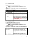
Envelope feeder service check
Service tip: Check the envelope feeder paper path for any debris, pieces of envelope and so on. If any other
options are installed make sure they are operating normally. If only the envelope feeder is failing to operate
correctly, continue with this service check, otherwise verify the interconnect card is functioning properly.
Service tip: The envelope feeder receives its +5 V dc operating voltage from the +24 V dc bulk at J1-7. If
+24 V dc is not present at J1-7, tray 1 is the only tray that is recognized.
Note: If a 260 Paper Jam Check Envelope message displays, check the “Sub error codes for 9xx and 2xx
error codes” on page 2-8.
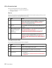
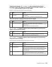
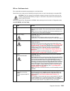
Printer does not recognize the envelope feeder as an attached input option
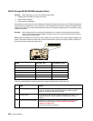
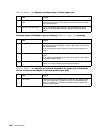
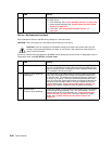
Operator panel displays 260.xx Paper Jam immediately when envelope feed is
requested—POST incomplete
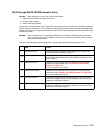
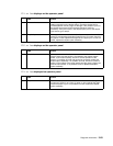
FRU Action
1 Envelope feeder Make sure the envelope feeder is correctly installed and mated to the
autoconnect at the front of the printer.
2
Front autoconnect on
printer
Check the connector for signs of damage to the connector or
contacts. If you find damage, replace the damaged cable/connector
assembly. Remove the envelope feeder and check the voltages at the
autoconnect on the front of the printer. If incorrect, check the
interconnect card. If correct, reinstall the envelope feeder and
continue with step 3.
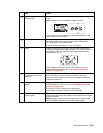
3
Autoconnect on the
envelope feeder
Check for damage to the connector or contacts. If you find damage,
replace the damaged cable/connector assembly. Disconnect the
autoconnect cable at J1 on the envelope system board and measure
the following voltages:
• J1-3 measures +5 V dc
• J1-5 measures +5 V dc
• J1-7 measures +24 V dc
If any of the voltages are incorrect, replace the autoconnect cable/
connector. If the voltages are correct, replace the envelope system
board.
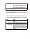
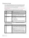
FRU Action
1 Pass thru sensor Check for any debris or pieces of envelope over the pass thru sensor.
Check for correct installation of the pass thru sensor flag. Make sure
the sensor cable is attached to the envelope system board. Perform
an envelope feeder sensor test to check both the sensor and sensor
flag.
Note: It may be necessary to use a small tool to actuate the sensor
flag because it is located under the front cover. Be careful not to
damage the flag.
If the test fails, check the flag for damage or binds. If incorrect,
replace the flag. If the flag is operating correctly, check the voltage at
J3-3. The voltage measures approximately +5 V dc. If incorrect,
replace the envelope system board. If correct, check the voltage at
J3-2. The voltage changes from 0 to +5 V dc when the flag is moved
in and out of the sensor. If incorrect, replace the sensor assembly. If
this does not fix the problem, replace the envelope system board.