


4-76 Service Manual
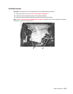
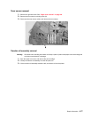
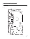
System board and inner shield removal
Warning: When replacing any one of the following components:
• Operator panel assembly (or upper front cover)
• System board assembly
• Interconnect card assembly
Only replace one component at a time. Replace the required component and perform a POR before replacing a
second component listed above. If this procedure is not followed, the printer will be rendered inoperable. Never
replace two or more of the components listed above without a POR after installing each one or the printer will be
rendered inoperable.
Warning: Never install and remove components listed above as a method of troubleshooting components.
Once a component has been installed in a printer, it can not be used in another printer. It must be
returned to the manufacturer.
Warning: Observe all ESD precautions while handling ESD-sensitive parts. See “Handling ESD-sensitive
parts” on page 4-1.
1. Remove the outer shield. See “Outer shield removal” on page 4-67.
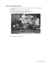
2. Disconnect all cables from the system board.
Note: Sometimes cables may be difficult to remove. Be careful not to damage the connectors.
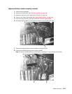
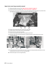
3. Remove all features and options from the interconnect card.
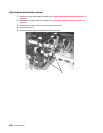
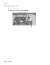
4. Depending on your printer model, remove the two small USB port mounting screws (A), the two parallel
port mounting screws (B), and the ethernet port mounting screw (C).
Note: You may not have all these screws in every model.
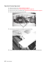
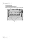
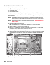
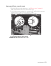
5. Remove the system board mounting screws, including the screw in the upper left corner (C), the two small
screws in the center top and bottom (D), and the three screws (E) (on the lower left and top and bottom
right).
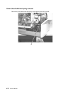
6. Remove the system board and inner shield.
AB D FE
C
F