


Diagnostic information 2-79
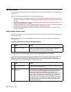
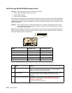
Charge roll service check
Service tip: Close and evenly spaced repetitive marks 47.19 mm (1.86 in.) apart, or spots on the page can be
caused by a damaged or contaminated dual charge roll.
Service tip: Make sure the right charge roll arm bushing is correctly installed and operates correctly.
To remove the charge roll:
1. Wrap a piece of plain white paper around the charge roll to prevent contamination or damage.
2. Carefully remove the roll by pressing outward and to the right on the charge roll link arm and remove the
charge roll from the right side charge roll bearing.
3. Remove the charge roll from the left side charge roll bearing and remove the roll from the printer. Leave the
paper wrapped around the charge roll until it is reinstalled.
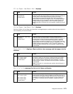
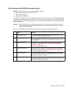
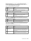
4
System board Replace the current system board with the original system board.
See “System board and inner shield removal” on page 4-76.
If the error remains, go to step 6.
5
Interconnect card assembly Replace the original interconnect card assembly with a new and not
previously installed interconnect card assembly. If the problem
remains, contact the next level of support.
6
System board Replace the original system board with a new and not previously
installed system board. If the problem remains, contact the next level
of support.
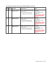
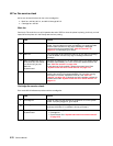
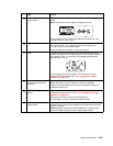
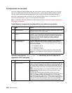
FRU Action
1 Charge roll assembly Check the charge roll for correct installation, toner buildup, marks,
cuts, or other signs of contamination or damage. Replace as
necessary.
2
Left side charge roll link Check the left side charge roll link assembly for correct assembly
operation. Check for damage to the arm or bearing assembly.
3
Right side charge roll link
Right charge roll bushing
Check the right side charge roll link assembly for correct assembly
operation. If incorrect, replace the charge roll link assembly with the
charge roll link assembly kit. If correct, check the right charge roll link
assembly bearing for signs of wear or contamination. Excessive
contamination could cause intermittent charging of the charge roll. If
incorrect, replace the link assembly. Check for continuity of the right
link assembly from the bearing to the charge roll high voltage contact
on the right side frame. If incorrect, replace the link assembly.
Make sure the charge roll bushing is installed and operating correctly.
Note: The screw that attaches the charge roll lead to the contact
must be secure.
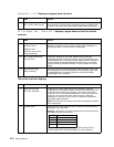
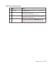
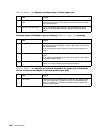
FRU Action