


2-74 Service Manual
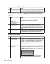
Ready—Bin x Full displays and paper feeds into bin x
271.xx Paper Jam - Check Bin 1 displays—paper does not feed into the bin
selected
990.xx Service Error displays
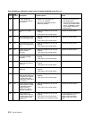
FRU Action
1 Bin x sensor
Bin x sensor control board
Check the sensor flag for binds. Make sure the sensor flag is not in
an up position. If the sensor flag is operating correctly, replace the bin
x sensor. If this does not fix the problem, replace the control board.
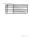
FRU Action
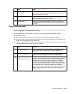
1 Deflector
Deflector spring
Deflector cover
Deflector cover spring
Shaft assemblies
Check all the bin parts for missing or loose springs, binds in the
deflector or deflector cover, broken or binding shaft assemblies, or
broken gear teeth. If incorrect, repair as necessary.
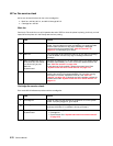
2
Bin x solenoid assembly
Control board
Check the solenoid for any binds. Make sure the solenoid is
contacting the latch correctly. If incorrect, repair as necessary. If the
solenoid appears to be operating mechanically, check the resistance
of the solenoid. It measures between 30 and 50 ohms. If incorrect,
replace the failing solenoid assembly. If correct, replace the control
board.
3
Mechanical linkage
Motor assembly
If the DC motor is functioning properly, check the gears, clutch, and
other linkage parts for correct operation and wear, broken gear teeth,
or damaged parts. If incorrect, replace the mechanical linkage
assembly/DC motor assembly.
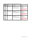
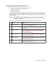
FRU Action
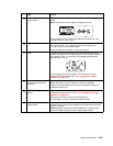
1 Mechanical linkage
DC motor assembly
Check the DC motor cable connector to be sure it is correctly
installed at J2 on the control board. If correct, disconnect J2 from the
control board and check the resistance of the motor on the cable
connector. J2-1 to J2-2 measures between 115 and 135 ohms. Also
check J2-1 and J2-4 to the motor case for shorts. If either the
resistance is incorrect or a short is found, replace the mechanical
linkage/DC motor assembly.
Note: If the DC motor is shorted, it may also be necessary to replace
the control board.
2
Control board Disconnect the motor cable J2 from the control board and check the
voltages at J2 on the board.
Warning: Use caution not to short adjacent pins on the connector as
damage to the board could result.
If any of the voltages are incorrect, replace the control board. If
correct, replace the mechanical linkage/ DC motor assembly.
Pin Measured (motor idle)
J2-1 +24 V dc
J2-2 +24 V dc
J2-5 +5 V dc
J2-6 +5 V dc