


Diagnostic information 2-95
High-capacity feeder input tray service check
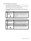
Note: Voltage measurements in the high-capacity feeder input tray service checks must be made with the high-
capacity feeder attached to the base printer to obtain accurate results.
Service tip: Be sure the paper size switch is set to the correct paper size setting and the rear paper guides are in
the correct locations for the size of paper installed in the high-capacity feeder tray.
Service tip: Check the other paper sources to be sure they are operating correctly.
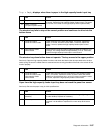
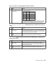
The base printer indicates a dead machine condition when the high-capacity input
tray is installed
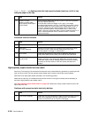
The base printer does not recognize that the high-capacity input tray is installed
FRU Action
1 AC line cord
AC jumper (HCIT to printer)
AC input and output
receptacles
AC wiring harness
If the base printer works normally using the AC line cord from the AC
wall outlet and does not work when using the AC jumper from the
HCIT, check the AC jumper cord. If defective, replace the cord. If not
defective, check the AC input and output receptacles and wiring
harness in the HCIT. Repair or replace the receptacles or AC wiring
harness as required.
Note: Make sure the ground wire is installed correctly from the AC
wiring harness to the frame of the HCIT and the nut and lock washer
are tightened.
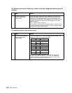
FRU Action
1 high-capacity feeder
autoconnect mechanical
check
Check the high-capacity feeder input tray to make sure it is mounted
correctly and is not pushed down into the frame assembly or
damaged. Be sure the high-capacity feeder input tray autoconnect is
properly connected to the high-capacity feeder tray option board
assembly.
2
Base printer or option
mounted above
Check the option or base printer autoconnect for signs of damage.
Repair the high-capacity option autoconnect as necessary.
3
LVPS
Option system board
Check the voltages at J11-2 and J11-4. The voltage measures
+24 V dc, If the voltage is correct, replace the high-capacity system
board assembly. If the voltage is incorrect, check the continuity of the
AC input cable to the LVPS. If correct, replace the LVPS assembly. If
incorrect, replace the AC cable to the input of the LVPS.