


2-92 Service Manual
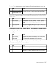
Fuser exit sensor service check
If any of the following codes are displayed, there is a potential problem in the area of the exit sensor: 201.00,
201.02, 201.10, 201.12, 201.22, 201.30, 201.32, 201.40, 201.41, 201.42, 201.50, 201.52, 201.92, 202.00,
202.02, 202.04, 202.10, 202.11, 202.12, 202.14, 202.20, 202.21, 202,22, 202.24. 202.30, 202.31, 202.32,
202.34, 202.40, 202.41, 202.42, 202.44, 202,50, 202.51, 202.52, 202.54, 202.90, 202.91, 202.92, and 202.94.
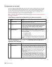
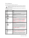
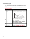
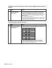
Fuser exit and fuser narrow media sensor status chart
3
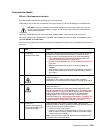
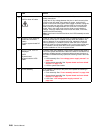
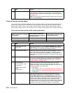
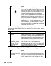
Fuser lamp Turn the printer off and allow the fuser assembly to cool. After the
fuser assembly cools down, turn the printer on. If you receive the
same error code, replace the fuser lamp. See “Fuser lamp removal”
on page 4-32.
Note: If the fuser lamp is replaced, allow the fuser to cool or a 925.xx
error could be displayed.
Printer not printing— no media
over sensors
Printer printing—media over
sensor(s), non-narrow media fed
through the printer
Printer printing—narrow media
fed through the printer
Exit sensor open Exit sensor closed Exit sensor closed
Narrow media sensor open Narrow media sensor closed Narrow media sensor open
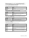
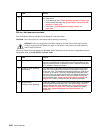
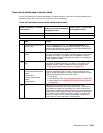
FRU Action
1 Fuser exit sensor (exit
sensor test)
Enter the Diagnostic mode, select BASE SENSOR TEST, select the
Exit Sensor to test for proper operation. If the exit sensor fails the
test, go to step 2. If the exit sensor passes, go to step 5.
2
Fuser exit sensor cable Check the fuser exit sensor cable for correct installation or for any
signs of damage to the cable or connectors. If no problem is found,
go to step 3. If a problem with the installation is found, install the
cable correctly. If damage to the cable or connectors is found, replace
the cable.
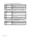
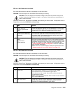
3
Fuser exit sensor flag Make sure the sensor flag is not binding and is operating properly. If
the sensor is operating properly, go to step 4. If it is not operating
properly, repair or replace the sensor assembly. See “Fuser exit
sensor removal” on page 4-28.
4
Fuser assembly
Fuser exit sensor cable
Fuser board
Fuser to system board
cable
System board
Check the continuity of the fuser exit sensor cable. If incorrect,
replace the cable; if correct check the continuity of the fuser to
system board cable. If incorrect, replace the cable; in correct, replace
the following FRUs in the order shown:
• Fuser board.
• Fuser assembly. See “Fuser assembly removal” on page 4-26.
• System board. See “System board and inner shield removal”
on page 4-76.
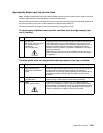
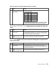
5
With the redrive assembly removed from the printer, enter the
Diagnostics mode and run the print test from tray 1 (for example,
select PRINT TESTS, Tray 1, and Continuous) and observe the
media as it passes over the exit and narrow media sensors. Check
that the sensor flags are operating correctly. If the sensor flags and
hardware are operating incorrectly, repair or replace the failing
sensor assembly. If no problem is found, check the fuser for any signs
of media in the fuser or any signs of toner or other contamination. If a
problem is found, clean or remove the debris or contamination.
FRU Action