


Diagnostic information 2-107
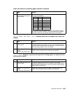
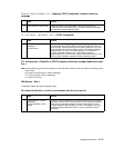
Operator panel display
Service tip: The printer has detected a problem with the system board, the operator panel cable (part of the
upper front cover hinge assembly), or the operator panel board if POST does not complete, the printer emits 5
beeps, and stops in a continuous pattern until the printer is turned off.
Note: If the operator panel is operating properly except for a pel or a few pels missing or broken, run the “Panel
Test” on page 3-7 from the hardware tests before continuing with this service check.
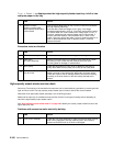
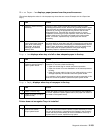
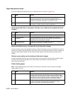
FRU Action
1 Operator panel cable Check for proper installation of the cable at the system board (J13)
and at the operator panel. Check the continuity of the operator panel
cable. If incorrect, replace the upper front cover hinge assembly. See
“Upper front cover hinge assembly removal” on page 4-78.
2
Operator panel display
blank, 5 beeps, LED off
Check for correct installation of the operator panel cable at J13 on
the system board. If incorrect, reinstall the cable properly. If correct,
measure the voltage at J13-2 on the system board. The voltage
should measure approximately +5 V dc. If incorrect, replace the
system board. “System board and inner shield removal” on
page 4-76. If correct, check continuity of the operator panel cable. If
the continuity is incorrect, replace the upper front hinge assembly. If
the continuity is correct, replace the operator panel board. See
“Operator panel board removal” on page 4-66.
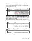
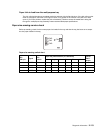
3
Operator panel display
blank, 5 beeps, LED on
Check for ground between J13-4 and ground. If correct, replace the
operator panel board. See “Operator panel board removal” on
page 4-66. If incorrect, check the operator panel cable. If the cable is
incorrect, replace the upper front cover hinge assembly. See “Upper
front cover hinge assembly removal” on page 4-78. If the correct,
replace the system board. See “System board and inner shield
removal” on page 4-76.
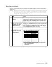
4
Operator panel all
diamonds, no beeps
Make sure a card is not plugged in backward. This condition causes
the printer to fail POST, displaying all diamonds on the operator panel
with no beeps.
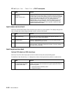
5
Operator panel all
diamonds, 5 beeps
Check the voltage at Pin J13-1 and J13-3. The voltage measures
approximately +3.3 V dc. If incorrect, replace the FRUs in the
following order:
• Operator panel board (see “Operator panel board removal” on
page 4-66) or the Upper front cover (see “Upper front cover
removal” on page 4-11).
• System board. See “System board and inner shield removal”
on page 4-76.
• Upper front cover hinge assembly. See “Upper front cover
hinge assembly removal” on page 4-78.