


Diagnostic information 2-81
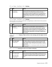
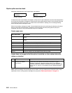
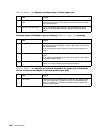
3
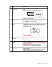
+5 V dc test point on the
system board
Check for approximately +5 V dc at the +5 V test point on the system
board.
Note: Use care not to short adjacent voltage test points.
If the voltage is correct, replace the system board assembly. If the
voltage is incorrect, go to step 4.
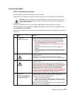
4
System board Check to make sure the LVPS cable is correctly installed at J27 on
the system board. If not, reseat and recheck the voltage at the
+5 V dc test point on the system board.
If test point does not measure +5 V dc, go to step 5.
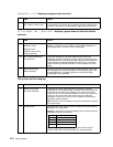
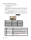
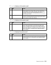
5
LVPS Unplug the AC line cord from the LVPS and disconnect the LVPS
cable to the system board. Reconnect the AC line cord and measure
the voltage on CN2-1 on the LVPS. The voltage should measure
approximately +5 V dc.
If the voltage is correct, go to step 6. If the voltage is incorrect,
replace the LVPS assembly. See “Low voltage power supply
removal” on page 4-54
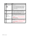
6
Features or option installed
on the interconnect card
assembly
Warning: Observe all the ESD precautions and turn the printer off
before any feature or option cards are removed or replaced.
Remove one option/feature at a time to help isolate the failing part.
Replace the faulty part.
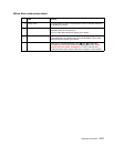
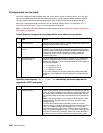
7
LVPS fuse F1 (primary
power)
Unplug the AC line cord, remove the LVPS from the printer, and
check the continuity of fuse F1. See “Low voltage power supply
removal” on page 4-54.
If continuity is correct, replace the LVPS assembly.
If the voltage is incorrect, replace the LVPS assembly.
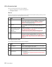
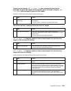
8
Loads connected to the
system board
Turn the printer off and disconnect each cable connected to the
system board and each option installed on the system board until the
problem is located.
Warning: When removing any card installed on the system board
observe all ESD precautions when handling these options.
FRU Action