


2-110 Service Manual
Output expander service check
Service tip: The majority of the mechanical components can be observed during operation by removing the left,
right, and system board covers. The output expander functions without the covers installed.
Make sure the option is correctly installed before attempting to service the unit. No jumpers should be installed
at connector J6 on the output expander board.
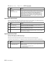
Problems with excessive static electricity buildup
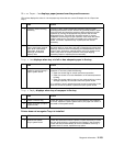
Printer does not recognize one or more output expander options as being installed
Service tip: If more than a single output expander option is installed, check each one to see if the printer
recognizes any single option as being installed. If the printer recognizes any of the output expander options then
the base printer autoconnect system is operating correctly and the problem is in the unrecognized expander
option.
202.xx Paper Jam Open Rear Door message displays; a sheet of paper is
jammed prior to the pass thru sensor flag
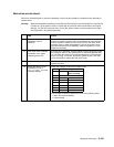
202.xx Paper Jam Open Rear Door message displays; a sheet of paper feeds out to
the standard bin even though bin x is selected; paper exits half way out of the redrive
Service tip: For this type of problem check the sub error codes. They can help isolate the problem. 202 Paper
Jam messages can also occur prior to the output expander pass thru sensor.
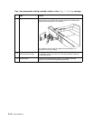
FRU Action
1 Output expander control
board cover
Check the output expander control board cover to make sure the
ESD brush ground lead is firmly attached to the output expander
frame. Also make sure the ESD brush is not loose.
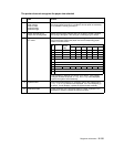
FRU Action
1 Output expander option Make sure the output expander option is the only option that is not
recognized by the base printer. If the output expander is the only
option not recognized by the printer, continue with step 2. If not,
check the autoconnects of the options not recognized and the
interconnect card and cable connections.
2
Output expander assembly
mechanical linkage
Check the autoconnects for damage, especially the connector pins.
Remove the left and right side covers. Remove the front control board
cover. Check the cables at J1A, J1B, J2A and J2B on the control
board to make sure they are attached securely and correctly.
Remove the output expander and check the voltages on the output
bin autoconnect located on the top left rear of the printer. Go to
“Autoconnect” on page 5-6. If the voltages are correct and the
problem persists, replace the output expander option.
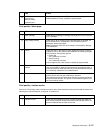
FRU Action
1 Output expander drive belt
Pulley drive belt
Idler pulley belt tension
spring
Check to ensure the output expander drive belt is correctly installed
on the drive pulley and belt idler pulley. Check the belt tension spring
to make sure it is not loose or broken. Repair as necessary.
2
Mechanical linkage
DC motor assembly
If the DC motor is functioning properly check the gears, clutch, and
other linkage parts for correct operation and wear, broken gear teeth,
or damaged parts. If incorrect, replace the output expander option.