


Diagnostic information 2-91
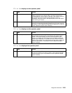
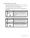
924.xx—Hot fuser service check
Error Code 923.xx, 924.xx, and 925.xx may display for a hot fuser failure.
CAUTION: .The fuser may be hot, use caution before removing or servicing.
CAUTION: There is a danger from hazardous voltage in the area of the printer where you are
working. Unplug the printer before you begin, or use caution if the printer must receive power in
order to perform the task.
Service tip: Set the Fuser Temperature to NORMAL before starting this service check. In Diagnostics mode, In
Diagnostics mode, select EP SETUP, and Fuser Temp.
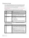
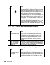
925.xx—Hot fuser service check
Error Code 923.xx, 924.xx, and 925.xx may display for a hot fuser failure.
CAUTION: .The fuser may be hot, use caution before removing or servicing.
CAUTION: There is a danger from hazardous voltage in the area of the printer where you are
working. Unplug the printer before you begin, or use caution if the printer must receive power in
order to perform the task.
Service tip: Set the Fuser Temperature to NORMAL before starting this service check. In Diagnostics mode, In
Diagnostics mode, select EP SETUP, and Fuser Temp.
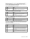
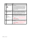
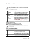
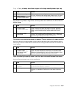
FRU Action
1 Fuser assembly
Fuser to system board
cable
Check the thermistor cable for correct installation to J5 on the fuser
card. If installed correctly, check for correct installation of J10 on the
system board. If all cables are installed correctly, go to step 2.
2
Fuser top cover assembly
(thermistor/thermistor cable
assembly)
Turn the printer off and disconnect the thermistor cable from J5 on
the fuser board. Measure the resistance between the two pins on the
thermistor cable, if the resistance measures infinity (open circuit),
replace the fuser top cover assembly.
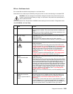
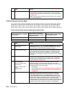
3
Fuser to system board
cable.
System board
Fuser assembly
Reconnect the thermistor cable to J5 on the fuser board. Disconnect
the fuser to system board cable from J10 on the system board and
measure the resistance between J10-3 and J10-4 on the cable. If the
resistance measures infinity (open circuit) check the continuity of pins
3 and 4 of the cable. If correct, replace the fuser assembly. See
“Fuser assembly removal” on page 4-26. If incorrect, replace the
fuser to system board cable.
Note: If the error code still displays, replace the system board. See
“System board and inner shield removal” on page 4-76.
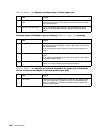
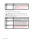
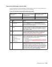
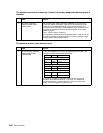
FRU Action
1 Fuser lamp If the fuser is 220 V machine a 115 V fuser may be installed.
If the printer is not a 115 V model, then go to step 2.
If the printer is a 220 V model, then check to make sure that the
correct lamp is installed.
Note: If the fuser lamp is replaced, allow the fuser to cool or a 925.xx
error could be displayed.
2
AC power source Check the AC power source to make sure it meets specifications. If
the AC power source does not meet specifications, inform the
customer. If it meets specifications, go to step 3.