


Diagnostic information 2-101
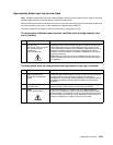
The printer does not recognize one or more output options as installed
Service tip: If more than a single output option is installed, check each one to see if the printer recognizes any
single option as installed. If the printer recognizes any of the output options, the base printer autoconnect
system is operating correctly. The problem is in the unrecognized option. Continue with this service check or go
to the service check for the failing output option.
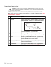
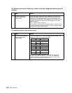
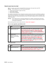
202.xx Paper Jam Open Rear Door displays and a sheet of paper is jammed prior
to the pass thru sensor flag or 202.xx Paper Jam Open Rear Door displays, a
sheet of paper feeds out to the standard bin even though bin x is selected and paper
exits half way out of the redrive assembly
Service tip: For this type of problem check the “Base printer sub error codes” on page 2-9. They can help
isolate the problem. A 202 paper jam message can also occur prior to the high-capacity output stacker pass thru
sensors.
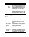
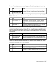
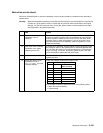
Remove Paper - Output Bin x Full displays; you may not be able to clear the
message
FRU Action
1 High-capacity stacker
feeder
Check the autoconnects, cables, and connectors of the option for any
signs of loose or damaged parts.
2
High-capacity output
stacker/mechanical linkage
assembly
Remove the left and right side covers and check all four
autoconnects for damage, especially the connector pins. Remove the
output option and check the voltages on the standard output bin
autoconnect located on the top left rear of the printer. Go to
“Autoconnect” on page 5-6. If the voltages are correct, reinstall the
output option and note the positions of the toroids on the autoconnect
cables on the upper and lower assemblies, and check the voltages on
the autoconnects. If all voltages are correct and the lower assembly
is failing, replace the lower control board. Otherwise, replace the
High-capacity output stacker option.
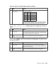
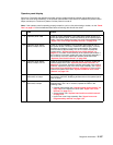
FRU Action
1 Lower Pass Thru Sensor/
Flag Assembly
Check the flag for correct operation, binding, broken parts, or
interference from the sensor cable. If incorrect, repair as necessary.
If correct, check to make sure the lower pass thru sensor is correctly
connected to J3 on the lower control board. Disconnect the pass thru
sensor cable and check the voltage at J3-3. The voltage measures
approximately +5 V dc. If incorrect, check the voltage at J3-2. The
voltage measures approximately 0 V dc. If incorrect, replace the
sensor assembly. If this does not fix the problem, replace the high-
capacity output stacker option.
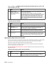
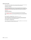
FRU Action
1 Dual output bin sensor flag
(upper assembly)
Check the flag for correct operation, binding, broken parts, or
interference from the sensor cable. If incorrect, repair as necessary.