


2-116 Service Manual
Parallel port service check
Run the “Parallel Wrap tests” on page 3-8.
Note: The Parallel Wrap Test is designed to check the parallel port hardware by using a wrap plug (P/N
1319128) and invoking the Parallel Diagnostic Test. This test helps isolate the printer from the parallel cable and
host. The test provides failure information on the display for approximately three seconds. If the test indicates
that a problem is detected, replace the controller board.
Print quality service check
Service tip: Before troubleshooting any print quality problems do the following:
• Install another print cartridge if available before proceeding with the service checks.
• Use Tray 1 to test for print quality of the base printer.
• Replace the charge roll if it is damaged or contaminated.
• Replace the transfer roll if it is damaged or contaminated.
• Make sure the fuser assembly is installed correctly.
• Verify proper paper type, texture, and weight settings for the media being used.
• Test the printer using plain paper (20 lb).
Select the following menu settings as indicated. Be sure and note the original settings so you can return the
printer to the original customer printer setup.
• Print Resolution: Set to 300 dpi (print quality problems should be checked at different resolution settings).
• Print Darkness: Set to NORMAL.
• Toner Saver: Set to OFF.
• PQET: Set to OFF.
• Fuser Temperature: Set to NORMAL.
• Test the printer using plain paper (20 lb).
An incorrect printer driver for the installed software can cause problems. Incorrect characters could print, and the
copy may not fit the page correctly.
Measure all voltages from the connector to printer ground. All voltages measured during the print cycle are
measured with the controller board removed while running the print test.
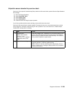
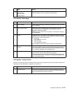
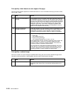
Print quality—all black page
Service tip: An all black page is generally caused by a problem in the high voltage system or an incorrect high
voltage in the printing process resulting in toner development on the entire photoconductor drum.
FRU Action
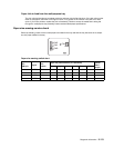
1 High voltage contacts Check the high voltage contacts on the right side frame to ensure
they fit securely and are not pitted, contaminated, or damaged. If
incorrect, replace the contact with one from the HV contact kit.
Screws and plastic blocks are included to attach the contacts to the
right side frame in the HV contact kit.
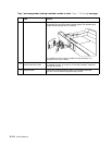
2
Charge roll conductive
bushing
Make sure the charge roll bushing is correctly installed in the right
charge roll arm.
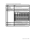
3
HVPS Check the voltages on J15-1 thru J15-8. If incorrect, replace the
system board.