Configuring PIM-DM 135
Example: PIM-DM Configuration
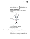
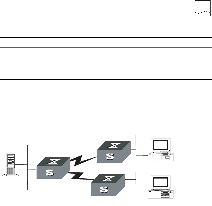
LS_A has a port carrying Vlan 10 to connect Multicast Source, a port carrying
Vlan11 to connect LS_B and a port carrying Vlan12 to connect LS_C. Configure to
implement multicast between Multicast Source and Receiver 1 and Receiver 2.
Figure 33 PIM-DM Configuration Networking
Configuration procedure
This section only provides the configuration for Switch A because the
configuration procedures for Switch B and Switch C are similar.
1 Enable the multicast routing protocol.
[SW7750]multicast routing-enable
2 Enable PIM-DM.
[SW7750]vlan 10
[SW7750-vlan10]port Ethernet 1/0/2 to Ethernet 1/0/3
[SW7750-vlan10]quit
[SW7750]vlan 11
[SW7750-vlan11]port Ethernet 1/0/4 to Ethernet 1/0/5
[SW7750-vlan11]quit
[SW7750]vlan 12
[SW7750-vlan12]port Ethernet 1/0/6 to Ethernet 1/0/7
[SW7750-vlan12]quit
[SW7750]interface vlan-interface 10
[SW7750-vlan-interface10]ip address 1.1.1.1 255.255.0.0
[SW7750-vlan-interface10]igmp enable
[SW7750-vlan-interface10]pim dm
[SW7750-vlan-interface10]quit
[SW7750]interface vlan-interface 11
[SW7750-vlan-interface11]ip address 2.2.2.2 255.255.0.0
[SW7750-vlan-interface11]igmp enable
[SW7750-vlan-interface11]pim dm
[SW7750-vlan-interface11]quit
[SW7750]interface vlan-interface 12
[SW7750-vlan-interface12]ip address 3.3.3.3 255.255.0.0
[SW7750-vlan-interface12]igmp enable
Disable the PIM-DM debugging undo debugging pim dm { alert | all
| mbr | mrt | timer | warning | {
recv | send } { all | assert |
graft | graft-ack | join | prune
} }
Table 144 Displaying and Debugging PIM-DM
Operation Command
Multicast
source
VLAN10
Switch A
VLAN12
VLAN11
Switch B
Switch C
Receiver 1
Receiver 2


