98 CHAPTER 5: IP ROUTING PROTOCOL OPERATION
Example: Typical RIP Configuration
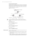
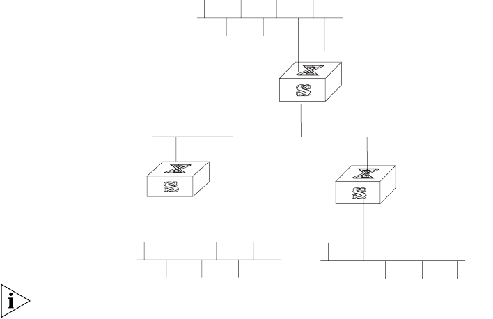
As shown in Figure 25, the Switch C connects to the subnet 117.102.0.0 through
the Ethernet port. The Ethernet ports of Switch A and Switch B are connected to
the network 155.10.1.0 and 196.38.165.0. Switch C, Switch A, and Switch B are
connected by Ethernet 110.11.2.0. Correctly configure RIP to ensure that Switch
C, Switch A, and Switch B can interconnect.
Figure 25 RIP Configuration
The following configuration only shows the operations related to RIP. Before
performing the following configuration, verify that the Ethernet link layer works
normally.
1 Configure RIP on Switch A:
[Switch A]rip
[Switch A-rip]network 110.11.2.0
[Switch A-rip]network 155.10.1.0
2 Configure RIP on Switch B:
[Switch B]rip
[Switch B-rip]network 196.38.165.0
[Switch B-rip]network 110.11.2.0
3 Configure RIP on Switch C:
[Switch C]rip
[Switch C-rip]network 117.102.0.0
[Switch C-rip]network 110.11.2.0
Troubleshooting RIP The Switch 7750 cannot receive update packets when the physical connection to
the peer routing device is normal.
■ RIP does not operate on the corresponding interface (for example, if the undo
rip work
command is executed) or this interface is not enabled through the
network command.
■ The peer routing device is configured for multicast mode (for example, the rip
version 2 multicast
command is executed) but the multicast mode has not
been configured on the corresponding interface of the local Ethernet switch.
Network address:
155.10.1.0/24
Interface address:
155.10.1.1/24
Switch A
Interface address:
110.11.2.1/24
Ethernet
Switch C
Network address:
110.11.2.2/24
Switch B
Network address:
196.38.165.0/24
Interface address:
196.38.165.1/24
Interface address:
117.102.0.1/16
Network address:
117.102.0.0/16


