Remote Interface Setup Preparation for Use
2-12 MS278XB OM
2-8 Remote Interface Setup
Most of the MS278XB functions (except power on/off and initialization of the hard disk) can be controlled
remotely by an external computer/controller via the IEEE-488.2 GPIB or a Local Area Network (LAN). The
information in this section pertains to the interface connections and cable requirements for the GPIB Setup
and LAN Setup. Refer to the Model MS278XB Programming Manual, Anritsu Part Number: 10410-00274, for
detailed information about remote programming of the MS278XB using these remote interface options; refer to
Chapter 8, Remote Operation for detailed information on operating the instrument remotely using Windows
Remote Desktop or third party applications, such as WebEX or PCAnywhere™.
GPIB Setup
The MS278XB GPIB operates with any IBM® PC compatible computer/controller equipped with a National
Instruments® GPIB-PCI I/IIA interface card and supporting software.
GPIB Interface Connection
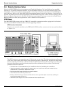
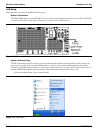
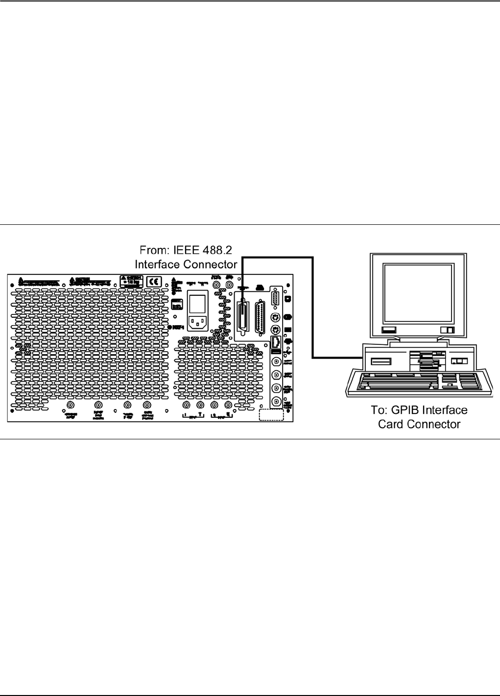
Connect your external controller to the IEEE 488.2 GPIB interface connector on the rear panel as shown
in Figure 2-11.
The GPIB system can accommodate up to 15 devices at any one time. To achieve maximum performance
on the bus, proper timing and voltage level relationships must be maintained. If either the cable length
between separate instruments or the accumulated cable length between all instruments is too long, the
data and control lines cannot be driven properly and the system may fail to perform. The following
guidelines should be observed:
• No more than 15 instruments may be installed on the bus (including the controller).
• Total accumulative cable length (in meters) may not exceed two times the number of bus
instruments or 20 meters—whichever is less.
• Individual cable length should not exceed 4 meters.
• 2/3 of the devices must be powered on.
• Devices should not be powered on while the bus is in operation (that is; actively sending or
receiving messages, data, etc.).
• Minimize cable lengths to achieve maximum data transfer rates.
Figure 2-11. GPIB Interface Connection


