


Rear Panel and Connector Diagrams Instrument Overview
3-38 MS278XB OM
3-5 Rear Panel and Connector Diagrams
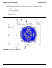
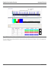
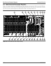
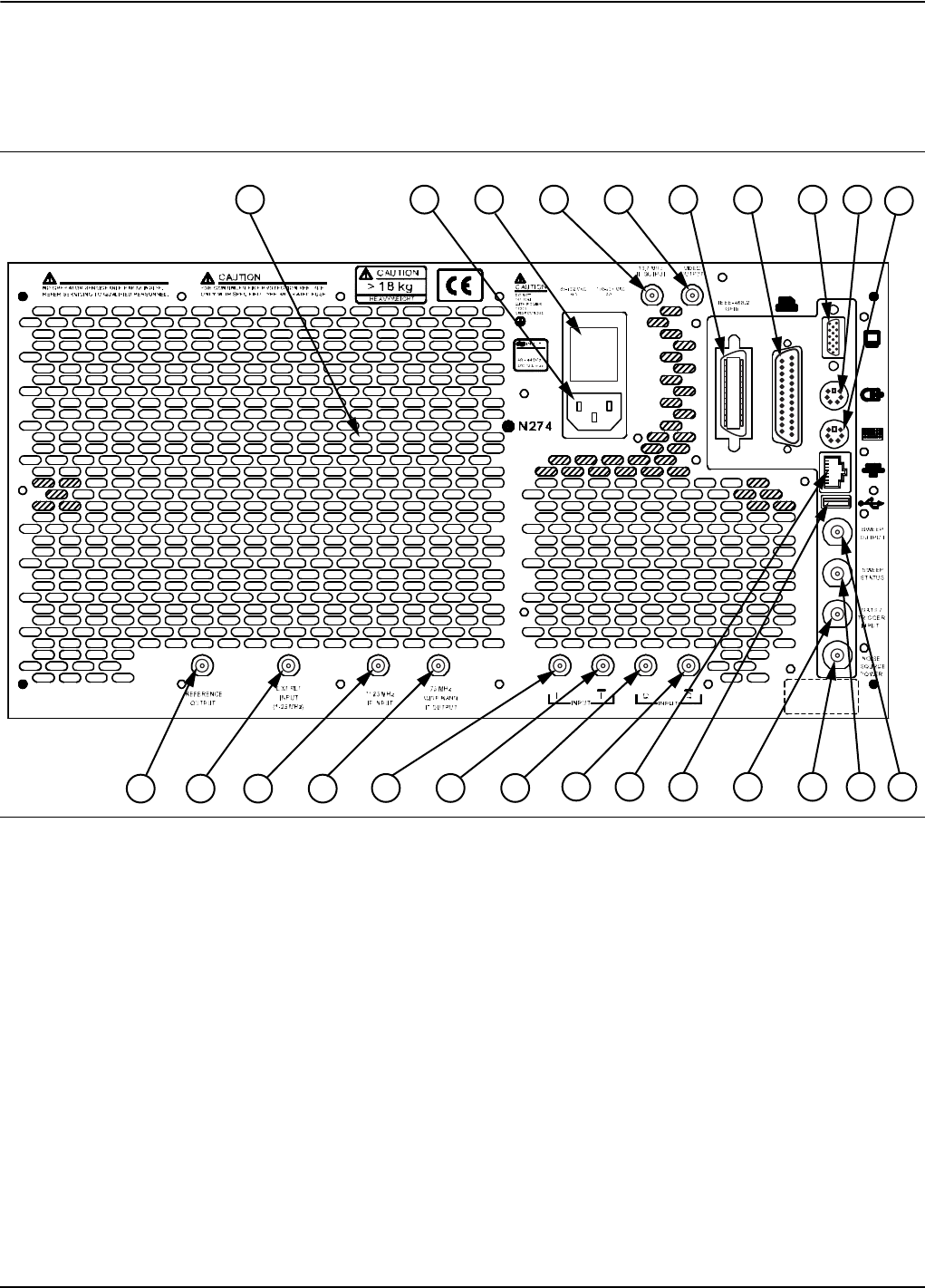
Figure 3-34, below, illustrates the MS278XB’s rear panel features and connectors. Table 3-9, on the following
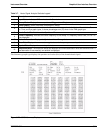
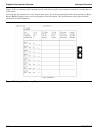
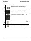
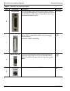
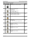
pages, describes the indices shown, lists Input/Output specifications for each connector, and lists the connector
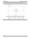
type. The connector pinout diagrams are illustrated in Table 3-10 through Table 3-16.
Figure 3-34. MS278XB Rear Panel Overlay Drawing
1 2 3 4 5 6
7
8
9
10
13 14
19
20 21
22
23
1211
24
15
16 17
18