Instrument Overview Rear Panel and Connector Diagrams
MS278XB OM 3-45
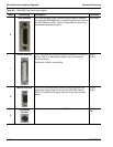
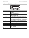
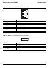
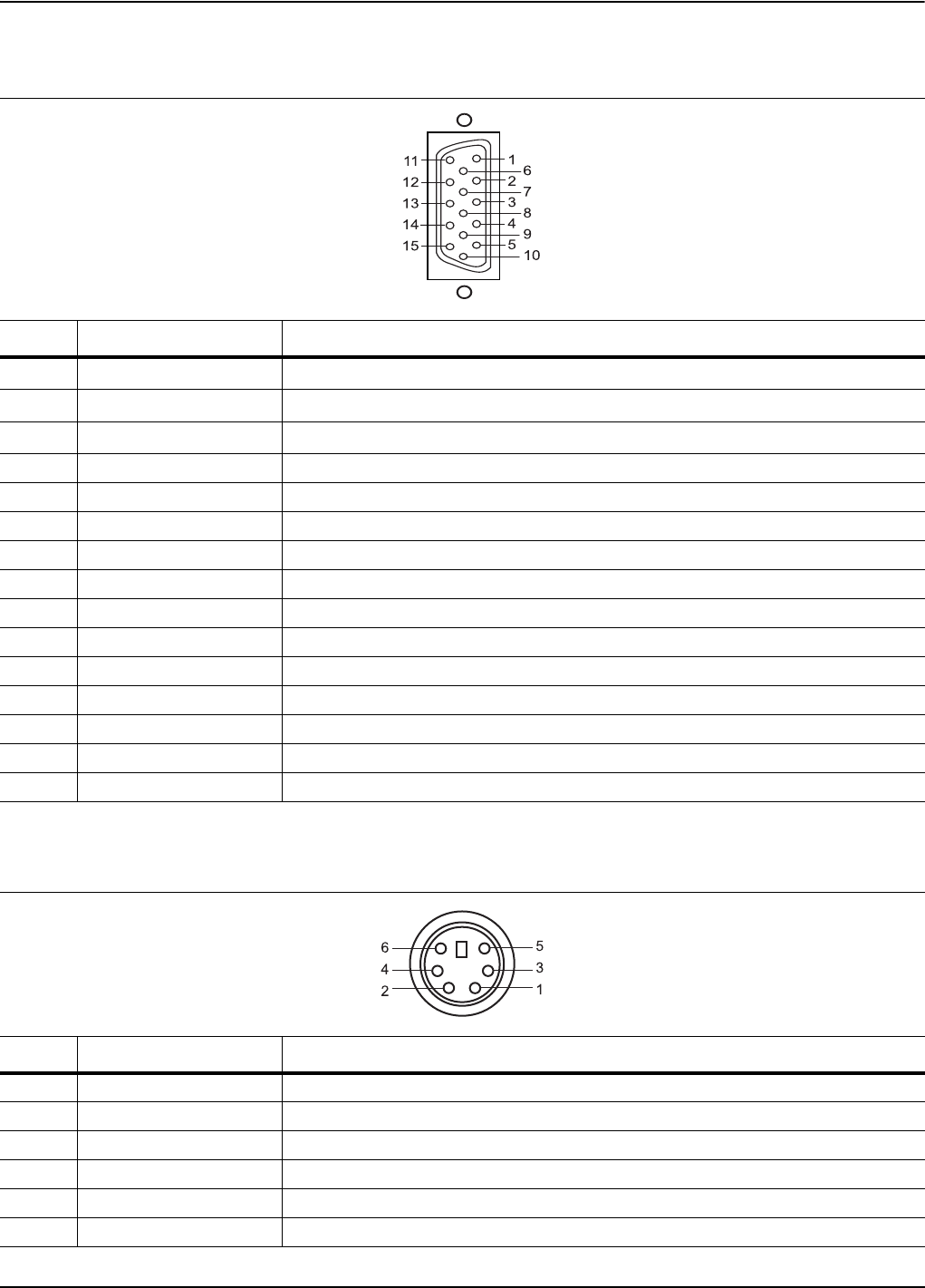
Table 3-13. Index 8: 15-pin XGA Connector Pinout Diagram
Pin Name Description
1Red
Red Video (75 Ω, 0.7 V
p-p
)
2Green
Green Video (75 Ω, 0.7 V
p-p
)
3Blue
Blue Video (75 Ω, 0.7 V
p-p
)
4 ID2 Monitor ID Bit 2
5 GND Ground
6 RGND Red Ground
7 GGND Green Ground
8 BGND Blue Ground
9 Key Connector Orientation Key
10 SGND Sync Ground
11 ID0 Monitor ID Bit 0
12 ID1 Monitor ID Bit 1
13 Hsync Horizontal Sync
14 Vsync Vertical Sync
15 ID3 Monitor ID Bit 3
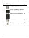
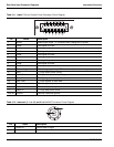
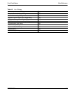
Table 3-14. Index 9 and 10: 6-pin PS2 Mouse and Keyboard Connector Pinout Diagram
Pin Name Description
1 Data Data signals from mouse or keyboard
2 – Not used
3 GND Ground
4 VCC +5 volts, 500 mA
5 Clock Sent data clock
6 – Not used


