


Rear Panel and Connector Diagrams Instrument Overview
3-46 MS278XB OM
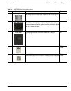
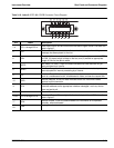
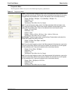
Table 3-15. Index 19: 8-pin Ethernet RJ45 Connector Pinout Diagram
Pin Name Description
1 TX+ Transmit data (> +3 volts)
2 TX– Transmit data (< –3 volts)
3 RX+ Receive data (< –3 volts)
4 – Not used (common mode termination)
5 – Not used (common mode termination)
6 RX– Receive data (< –3 volts)
7 – Not used (common mode termination)
8 – Not used (common mode termination)
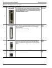
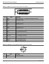
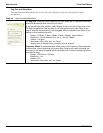
Table 3-16. Index 20: 4-pin USB Type A Connector Pinout Diagram
PIN Name Description
1 VCC +5 volts, 500 mA
2 –Data Data input
3 +Data Data output
4 GND Ground