


Instrument Overview Rear Panel and Connector Diagrams
MS278XB OM 3-43
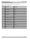
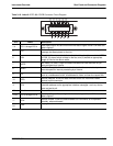
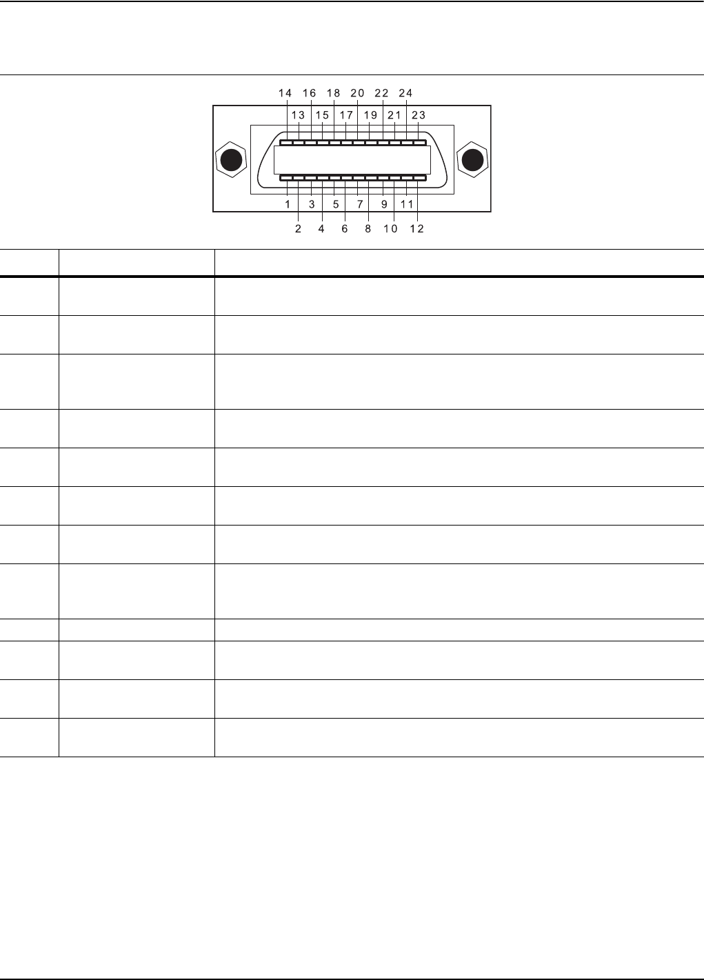
Table 3-10. Index 6: IEEE 488.2 GPIB Connector Pinout Diagram
Pin Name Description
1-4 DIO 1 through DIO 4
Data Input/Output. Bits are HIGH when the data is logical 0 and LOW when the
data is logical 1.
5EOI
End or Identify. A low-true state indicates that the last byte of a multi byte
message has been placed on the line.
6DAV
Data Valid. A low-true state indicates that the talker has (1) sensed that NRFD
is LOW, (2) placed a byte of data on the bus, and (3) waited an appropriate
length of time for the data to settle.
7NRFD
Not Ready For Data. A high-true state indicates that valid data has not yet
been accepted by a listener.
8NDAC
Not Data Accepted. A low-true state indicates that the current data byte has
been accepted for internal processing by a listener.
9IFC
Interface Clear. A low-true state places all bus instruments in a known state—
such as, unaddressed to talk, unaddressed to listen, and service request idle.
10 SRQ
Service Request. A low-true state indicates that a bus instrument needs
service from the controller.
11 ATN
Attention. A low-true state enables the controller to respond to both its own
listen/talk address and to appropriate interface messages—such as, device
clear and serial poll.
12 Shield Ground Point.
13-16 DIO 5 through DIO 8
Data Input/Output. Bits are high with the data is logical 0 and LOW when the
data is logical 1.
17 REN
Remote Enable. A low-true state enables bus instruments to be operated
remotely, when addressed.
18 to
24
GND
Logic ground.