


SECTION 7. MEASUREMENT PROGRAMMING EXAMPLES
7-8
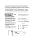
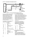
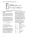
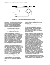
FIGURE 7.10-1. 3 Wire Half Bridge Used to Measure 100 ohm PRT
7.10 100 OHM PRT IN 3 WIRE HALF
BRIDGE
The temperature measurement requirements in
this example are the same as in Section 7.9. In
this case, a three wire half bridge, Instruction 7,
is used to measure the resistance of the PRT.
The diagram of the PRT circuit is shown in Fig.
7.10-1.
As in the example in Section 7.9, the excitation
voltage is calculated to be the maximum
possible, yet allow the +25 mV measurement
range. The 10 kohm resistor has a tolerance of
±1%; thus, the lowest resistance to expect from
it is 9.9 kohms. We calculate the maximum
excitation voltage (V
x
) to keep the voltage drop
across the PRT less than 25 mV:
0.025V > V
x
115.54/(9900+115.54);
V
x
< 2.17 V
The excitation voltage used is 2.1 V.
The multiplier used in Instruction 7 is
determined in the same manner as in Section
7.9. In this example, the multiplier (R
f
/R
0
) is
assumed to be 100.93.
The 3 wire half bridge compensates for lead
wire resistance by assuming that the resistance
of wire A is the same as the resistance of wire
B. The maximum difference expected in wire
resistance is 2%, but is more likely to be on the
order of 1%. The resistance of R
s
calculated
with Instruction 7, is actually R
s
plus the
difference in resistance of wires A and B. The
average resistance of 22 AWG wire is 16.5
ohms per 1000 feet, which would give each 500
foot lead wire a nominal resistance of 8.3 ohms.
Two percent of 8.3 ohms is 0.17 ohms.
Assuming that the greater resistance is in wire
B, the resistance measured for the PRT (R
0
=
100 ohms) in the ice bath would be 100.17
ohms, and the resistance at 40°C would be
115.71. The measured ratio R
s
/R
0
is 1.1551;
the actual ratio is 115.54/100 = 1.1554. The
temperature computed by Instruction 16 from
the measured ratio would be about 0.1°C lower
than the actual temperature of the PRT. This
source of error does not exist in the example in
Section 7.9, where a 4 wire half bridge is used
to measure PRT resistance.
The advantages of the 3 wire half bridge are
that it only requires 3 lead wires going to the
sensor and takes 2 single-ended input
channels, whereas the 4 wire half bridge
requires 4 wires and 2 differential channels.
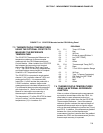
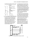
PROGRAM
01: P7 3 Wire Half Bridge
01: 1 Rep
02: 23 25 mV 60 Hz rejection Range
03: 1 IN Chan
04: 1 Excite all reps w/EXchan 1
05: 2100 mV Excitation
06: 1 Loc [:Rs/Ro ]
07: 100.93 Mult
08: 0 Offset
02: P16 Temperature RTD
01: 1 Rep
02: 1 R/Ro Loc Rs/Ro
03: 2 Loc [:TEMP C ]
04: 1 Mult
05: 0 Offset