


CR10 OVERVIEW
OV-9
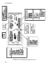
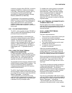
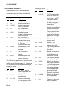
OV2.2 CR10 INSTRUCTION TYPES
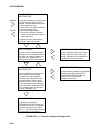
Figure OV2.1-1 illustrates the use of three
different instruction types which act on data.
The fourth type, Program Control, is used to
control output times and vary program
execution. Instructions are identified by
numbers.
1. INPUT/OUTPUT INSTRUCTIONS (1-28,
101-104, Section 9) control the terminal
strip inputs and outputs (the sensor is the
source, Figure OV1.1-2), storing the results
in Input Storage (destination). Multiplier
and offset parameters allow conversion of
linear signals into engineering units. The
Digital I/O Ports are also addressed with
I/O Instructions.
2. PROCESSING INSTRUCTIONS (30-66,
Section 10) perform numerical operations
on values located in Input Storage (source)
and store the results back in Input Storage
(destination). These instructions can be
used to develop high level algorithms to
process measurements prior to Output
Processing.
3. OUTPUT PROCESSING INSTRUCTIONS
(69-82, Section 11) are the only
instructions which store data in Final
Storage (destination). Input Storage
(source) values are processed over time to
obtain averages, maxima, minima, etc.
There are two types of processing done by
Output Instructions: Intermediate and
Final.
Intermediate processing normally takes
place each time the instruction is executed.
For example, when the Average Instruction
is executed, it adds the values from the
input locations being averaged to running
totals in Intermediate Storage. It also keeps
track of the number of samples.
Final processing occurs only when the
Output Flag is high. The Output
Processing Instructions check the Output
Flag. If the flag is high, final values are
calculated and output. With the Average,
the totals are divided by the number of
samples and the resulting averages sent to
Final Storage. Intermediate locations are
zeroed and the process starts over. The
Output Flag, Flag 0, is set high by a
Program Control Instruction which must
precede the Output Processing Instructions
in the user entered program.
4. PROGRAM CONTROL INSTRUCTIONS
(83-98, Section 12) are used for logic
decisions and conditional statements. They
can set flags, compare values or times,
execute loops, call subroutines, conditionally
execute portions of the program, etc.
OV2.3 PROGRAM TABLES, EXECUTION
INTERVAL AND OUTPUT INTERVALS
Programs are entered in Tables 1 and 2.
Subroutines, called from Tables 1 and 2, are
entered in Subroutine Table 3. The size of
each table is flexible, limited only by the total
amount of program memory. If Table 1 is the
only table programmed, the entire program
memory is available for Table 1.
Table 1 and Table 2 have independent
execution intervals, entered in units of seconds
with an allowable range of 1/64 to 8191
seconds. Subroutine Table 3 has no execution
interval; subroutines are only executed when
called from Table 1 or 2.
OV2.3.1 THE EXECUTION INTERVAL
The execution interval specifies how often the
program in the table is executed, which is
usually determined by how often the sensors
are to be measured. Unless two different
measurement rates are needed, use only one
table. A program table is executed sequentially
starting with the first instruction in the table and
proceeding to the end of the table.