


SECTION 2. INTERNAL DATA STORAGE
2-3
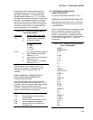
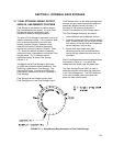
Output Processing Instructions store data into
Final Storage only when the Output Flag is set.
The string of data stored each time the Output
Flag is set is called an OUTPUT ARRAY. The
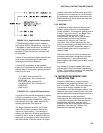
first data point in the output array is a 3 digit
OUTPUT ARRAY ID. This ID number is set in
one of two ways:
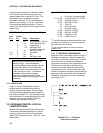
1. In the default condition, the ID consists of
the program table number and the
Instruction Location Number of the
instruction which set the Output Flag for
that particular array of data. For example,
the ID of 118 in Figure 2.1-2 indicates that
the 18th instruction in Table 1 set the
Output Flag.
2. The output array ID can be set by the user
with the second parameter of Instruction 80
(Section 11). The ID can be set to any
positive integer up to 511. This option
allows the user to make the output array ID
independent of the programming. The
program can be changed (instructions
added or deleted) without changing the
output array ID. This avoids confusion
during data reduction, especially on long
term projects where program changes or
updates are likely.
FIGURE 2.1-2. Output Array ID
NOTE: If Instruction 80 is used to
designate the active Final Storage Area
and parameter 2 is 0, the output array ID is
determined by the position of Instruction 80
or by the position of the instruction setting
the Output Flag, whichever occurs last.
A start-of-array marker ($ in Figure 2.1-1) is
written into Final Storage with the Output Array
ID. This marker is used as a reference point
from which to number the data points of the
output array. The start of array marker occupies
the same Final Storage location as the Array ID
and is transparent for all user operations.
Data are stored in Final Storage before being
transmitted to an external device. There are 5
pointers for each Final Storage Area which are
used to keep track of data transmission. These
pointers are:
1. Display Pointer (DPTR)
2. Tape Pointer (TPTR)
3. Printer Pointer (PPTR)
4. Telecommunications (Modem) Pointer
(MPTR)
5. Storage Module Pointer (SPTR)
The DPTR is used to recall data to the keyboard/
display. The positioning of this pointer and data
recall are controlled from the keyboard (*7 Mode).
The TPTR is used to control data transmission
to a cassette tape recorder. When on-line tape
transfer is activated (Instruction 96, option 00),
data is transmitted to tape whenever the DSP is
a minimum of 512 memory locations ahead of
the TPTR. The TPTR may also be positioned
via the keyboard for manually initiated data
transfer to tape (*8 Mode).
The PPTR is used to control data transmission
to a printer or other serial device. Whenever
on-line printer transfer is activated (Instruction
96), data between the PPTR and DSP are
transmitted. The PPTR may also be positioned
via the keyboard for manually initiated data
transmission (*8 Mode).
The MPTR is used in transmitting data over a
telecommunications interface. When
telecommunications is first entered, the MPTR is
set to the same location as the DSP. Positioning
of the MPTR is then controlled by commands from
the external calling device (Section 5.1).
The SPTR is used to control data transmission to a
Storage Module. When on-line transfer is activated
by Instruction 96, data is transmitted each time an
output array is stored in Final Storage IF THE
STORAGE MODULE IS CONNECTED TO THE
CR10. If the Storage Module is not connected, the
CR10 does not transmit the data nor does it
advance the SPTR to the new DSP location. It
saves the data until the Storage Module is
connected. Then, during the next execution of
Instruction 96, the CR10 outputs all of the data
between the SPTR and the DSP and updates the
SPTR to the DSP location (Section 4.1)
The SPTR may also be positioned via the
keyboard for manually initiated data transfer to
the Storage Module (*8 Mode, Section 3.2.3).