


SECTION 13. CR10 MEASUREMENTS
13-12
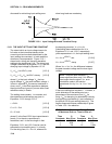
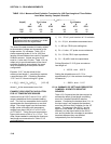
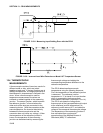
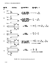
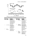
FIGURE 13.3-8. Measuring Input Settling Error with the CR10
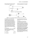
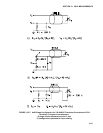
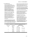
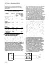
FIGURE 13.3-9. Incorrect Lead Wire Extension on Model 107 Temperature Sensor
13.4 THERMOCOUPLE
MEASUREMENTS
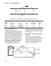
A thermocouple consists of two wires, each of a
different metal or alloy, which are joined
together at each end. If the two junctions are at
different temperatures, a voltage proportional to
the difference in temperatures is induced in the
wires. When a thermocouple is used for
temperature measurement, the wires are
soldered or welded together at the measuring
junction. The second junction, which becomes
the reference junction, is formed where the
other ends of the wires are connected to the
measuring device. (With the connectors at the
same temperature, the chemical dissimilarity
between the thermocouple wire and the
connector does not induce any voltage.) When
the temperature of the reference junction is
known, the temperature of the measuring
junction can be determined by measuring the
thermocouple voltage and adding the
corresponding temperature difference to the
reference temperature.
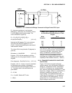
The CR10 determines thermocouple
temperatures using the following sequence.
First, the temperature of the reference junction
is measured. The reference junction
temperature in °C is stored in an input location
which is accessed by the thermocouple
measurement instruction (Instruction 13 or 14).
The CR10 calculates the voltage that a
thermocouple of the type specified would output
at the reference junction temperature if its
reference junction were at 0°C, and adds this
voltage to the measured thermocouple voltage.
The temperature of the measuring junction is
then calculated from a polynomial
approximation of the National Bureau of
Standards (NBS) TC calibrations.