


SECTION 8. PROCESSING AND PROGRAM CONTROL EXAMPLES
8-3
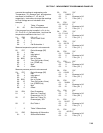
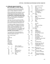
Input Location Labels:
1:Rain (mm)
2:15min tot
* 1 Table 1 Programs
01: 60 Sec. Execution Interval
01: P3 Pulse
01: 1 Rep
02: 1 Pulse Input Chan
03: 2 Switch Closure
04: 1 Loc [:Rain (mm)]
05: .254 Mult
06: 0 Offset
02: P92 If time is
01: 0 minutes into a
02: 15 minute interval
03: 10 Set high Flag 0 (output)
03: P80 Set Active Storage Area
01: 3 Input Storage Area
02: 2 Array ID or location
04: P72 Totalize
01: 1 Rep
02: 1 Loc Rain (mm)
05: P89 If X<=>F
01: 2 X Loc 15min tot
02: 2 <>
03: 0 F
04: 30 Then Do
06: P80 Set Active Storage Area
01: 1 Final Storage Area 1
02: 25 Array ID or location
07: P77 Real Time
01: 110 Day,Hour-Minute
08: P70 Sample
01: 1 Reps
02: 2 Loc 15min tot
09: P95 End
10: P End Table 1
8.3 USING CONTROL PORTS AND
LOOP TO RUN AM416
MULTIPLEXER
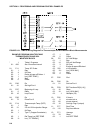
This example uses an AM416 to measure 16
copper-constantan thermocouples and 16
Model 223 soil moisture blocks. The sensors
are read every ten minutes and the average
value output once an hour. The multiplexer is
housed in an AM-ENCT enclosure to minimize
thermocouple errors created by thermal
gradients. A 107 Temperature Probe is
centrally located on the multiplexer board and
used as a thermocouple temperature reference.
The AM416 switches the 223 moisture block
out of the circuit when it is not being measured.
This eliminates the need for the blocking
capacitors used in the model 227 soil moisture
block. The 223 blocks are about one fifth the
cost of the 227 blocks.
Control ports are used to reset the AM416 and
clock it through its channels. The sequence of
the program is:
• Measure the 107 probe located at the
AM416 for TC temperature reference.
• CR10 sets the port high which resets the
AM416.
• A loop is entered; within each pass:
• The port clocking the AM416 is pulsed.
• The connected TCs and moisture blocks
are measured.
• CR10 sets the port controlling AM416 reset
low.
• Soil moisture measurements are converted
to block resistances.
The input location in which the temperature and
soil moisture measurements are stored is
indexed to the loop counter (Instruction 87,
Section 12). An indexed location is
incremented by one with each pass through the
loop. For example, on the first pass
temperature is stored in Location 2, and soil
moisture in Location 18. On the second pass
temperature is stored in Location 3, and soil
moisture in Location 19. After 16 loop passes,
temperature and soil moisture measurements
occupy Locations 2 through 17 and 18 through
33, respectively.
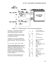
Connections are shown in Figure 8.3-1.