


SECTION 9. INPUT/OUTPUT INSTRUCTIONS
9-4
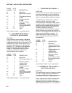
PARAM. DATA
NUMBER TYPE DESCRIPTION
01: 2 Repetitions
02: 2 Range Code (Table 9-
1)
03: 2 Single-ended channel
number
04: 2 Excitation channel
number
05: 4 Excitation voltage
(millivolts)
06: 4 Input location number
for first measurement
07: FP Multiplier
08: FP Offset
Input locations altered: 1 per measurement
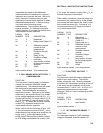
*** 6 FULL BRIDGE WITH SINGLE ***
DIFFERENTIAL MEASUREMENT
FUNCTION
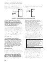
This Instruction is used to apply an excitation
voltage to a full bridge and make a differential
voltage measurement of the bridge output. The
measurement is made with the polarity of the
excitation voltage both positive and negative
(Figure 13.5-1). The result is 1000 times the
ratio of the measurement to the excitation
voltage. A 1 before the excitation channel
number (1X) causes the channel to be
incremented with each repetition.
PARAM. DATA
NUMBER TYPE DESCRIPTION
01: 2 Repetitions
02: 2 Range code (Table 9-1)
03: 2 Differential channel
number for first
measurement
04: 2 Excitation channel
number
05: 4 Excitation voltage
(millivolts)
06: 4 Input location number
for first measurement
07: FP Multiplier
08: FP Offset
Input locations altered: 1 per measurement
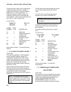
*** 7 THREE WIRE HALF BRIDGE ***
FUNCTION
This Instruction is used to determine the ratio of
the sensor resistance to a known resistance
using a second voltage sensing wire from the
sensor to compensate for lead wire resistance.
The measurement sequence is to apply an
excitation voltage, make two voltage
measurements on two adjacent single-ended
channels, the first on the reference resistor and
the second on the voltage sensing wire from
the sensor (Figure 13.5-1), then reverse the
excitation voltage and repeat the
measurements. The two measurements are
used to calculate the resulting value, which is
the ratio of the voltage across the sensor to the
voltage across the reference resistor. A 1
before the excitation channel number (1X)
causes the channel to be incremented with
each repetition.
PARAM. DATA
NUMBER TYPE DESCRIPTION
01: 2 Repetitions
02: 2 Range code for both
measurements (Table
9-1)
03: 2 Single-ended channel
number for first
measurement
04: 2 Excitation channel
05: 4 Excitation voltage
(millivolts)
06: 4 Input location number
for first measurement
07: FP Multiplier
08: FP Offset
Input locations altered: 1 per measurement
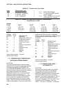
*** 8 DIFFERENTIAL VOLTAGE WITH ***
EXCITATION AND DELAY
FUNCTION
This measurement consists of applying a single
excitation voltage, delaying a specified time,
and making a differential voltage measurement.
The result stored is the voltage measured.
"Delay" (Parameter 5) refers to increasing the
signal settling time by increasing the time
between the start of excitation and the start of
signal integration (Section 13.2). If a delay of 0