


SECTION 3. INSTRUCTION SET BASICS
3-2
Location or Port the instruction acts on.
Normally the loop counter is incremented by 1
after each pass through the loop. Instruction
90, Step Loop Index, allows the increment step
to be changed. See Instructions 87 and 90,
Section 12, for more details.
To index an input location (4 digit integer) or set
port command (2 digit integer) parameter, C or
"-" is pressed after keying the value but before
entering the parameter. Two minus signs (-)
will be displayed to the right of the parameter.
3.5 VOLTAGE RANGE AND
OVERRANGE DETECTION
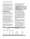
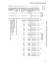
The voltage RANGE code parameter on
Input/Output Instructions is used to specify the
full scale range of the measurement and the
integration period for the measurement (Table
3.5-1).
The full scale range selected should be the
smallest that will accommodate the full scale
output of the sensor being measured. Using
the smallest possible range will result in the
best resolution for the measurement.
Four different integration sequences are
possible. The relative immunity of the
integration sequences to random noise is: 60
Hz rej. = 50 Hz rej. > 2.72ms integ. > 272 µs
integ. The 60 Hz rejection integration rejects
noise from 60 Hz AC line power. The 50 Hz
rejection is for countries whose electric utilities
operate at 50 Hz (Section 13.1).
When a voltage input exceeds the range
programmed, the value which is stored is set to
the maximum negative number and displayed
as -99999 in high resolution or -6999 in low
resolution.
An input voltage greater than +5 volts on one of
the analog inputs will result in errors and
possible overranging on the other analog
inputs. Voltages greater than 16 volts may
permanently damage the CR10.
NOTE: Voltages in excess of 5.5 volts
applied to a control port can cause the
CR10 to malfunction.
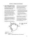
3.6 OUTPUT PROCESSING
Most Output Processing Instructions require
both an Intermediate Data Processing
operation and a Final Data Processing
operation. For example, when the Average
Instruction, 71, is initiated, the intermediate
processing operation increments a sample
count and adds each new Input Storage value
to a cumulative total residing in Intermediate
Storage. When the Output Flag is set, the final
processing operation divides the cumulative
total by the number of samples to find the
average. The average is then stored in final
storage and the cumulative total and number of
samples are set to zero in Intermediate
Storage.
Final Storage Area 1 (Sections 1.5, 2.1) is the
default destination of data output by Output
Processing Instructions. Instruction 80 may be
used to direct output to either Final Storage
Area 2 or to Input Storage.
Output Processing Instructions requiring
intermediate processing sample the specified
input location(s) each time the Output
Instruction is executed, NOT each time the
location value is updated by an I/O Instruction.
For example: Suppose a temperature
measurement is initiated by Table 1 which has
an execution interval of 1 second.
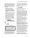
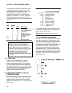
TABLE 3.5-1. Input Voltage Ranges and Codes
Range Code Full Scale Range Resolution*
Slow Fast
2.72ms 250 us 60 Hz 50 Hz
Integ. Integ. Reject. Reject.
1112131 ±2.5 mV 0.33 µV
2122232 ±7.5 mV 1. µV
3132333 ±25 mV 3.33 µV
4142434 ±250 mV 33.3 µV
5152535±2500 mV 333. µV
* Differential measurement, resolution for single-ended measurement is twice value shown.