


SECTION 6. 9-PIN SERIAL INPUT/OUTPUT
6-2
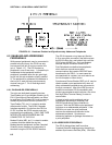
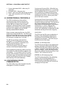
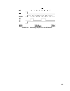
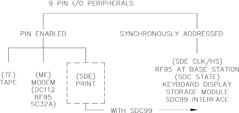
FIGURE 6.2-1. Hardware Enabled and Synchronously Addressed Peripherals
6.2 ENABLING AND ADDRESSING
PERIPHERALS
While several peripherals may be connected in
parallel to the 9-pin port, the CR10 has only
one transmit line (pin 9) and one receive line
(pin 4, Table 6.1-1). The CR10 selects a
peripheral in one of two ways: 1) A specific pin
is dedicated to that peripheral and the
peripheral is enabled when the pin goes high;
we will call this pin-enabled or simply enabled.
2) The peripheral is addressed; the address is
sent on pin 9, each bit being synchronously
clocked using pin 7. Pin 6 is set high while
addressing.
6.2.1 PIN-ENABLED PERIPHERALS
Two pins are dedicated to specific devices,
Tape Enable (pin 8) and Modem Enable (pin 5).
Pin 6 (Synchronous Device Enable) can either
be used as a Print Enable OR it can be used to
address Synchronous Devices (Section 6.6).
Tape Enable (TE), pin 8, is raised to enable
data transfer to tape. The SC92A Cassette
Interface regulates 12 volts from the CR10 to
6V DC to power the RC35 recorder and also
provides signal conditioning. ONLY ONE TAPE
INTERFACE AND RECORDER MAY BE
CONNECTED TO THE CR10.
Modem Enable (ME), pin 5, is raised to enable
a modem that has raised the ring line.
Modem/terminal peripherals include Campbell
Scientific phone modems and computers or
terminals using the SC32A RS232 interface.
The CR10 interprets a ring interrupt (Section
6.3) to come from a modem if the device raises
the CR10's Ring line, and holds it high until the
CR10 raises the ME line. Only one modem/
terminal may be connected to the CR10.
Print Peripherals are defined as peripherals
which have an asynchronous serial
communications port used to RECEIVE data
transferred by the CR10. In most cases the
print peripheral is a printer, but could also be an
on-line computer or other device.
Synchronous Device Enable (SDE), pin 6, may be
used to enable a print peripheral only when no
other addressable peripherals are connected to
the 9-pin connector. Use of the SDE line as an
enable line maintains CR10 compatibility with
printer-type peripherals which require a line to be
held high (Data Terminal Ready) in order to
receive data.
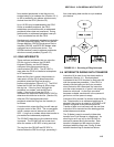
If output to both a print peripheral and an
addressable peripheral is necessary the
SDC99 Synchronous Device Interface is
required. With the SDC99 the print peripheral
functions as an addressable peripheral. If the
SDC99 is not used, the print peripheral
receives the address and data sent to the
addressed peripheral. Synchronous
addressing appears as garbage characters on
a print peripheral.
6.2.2 ADDRESSED PERIPHERALS
The CR10 distinguishes itself from other
Campbell Scientific dataloggers by the ability to
address Synchronous Devices (SDs). SDs differ