


SECTION 7. MEASUREMENT PROGRAMMING EXAMPLES
7-16
The following calculations are based on using a
Geokon model 4500 Vibrating Wire sensor. An
individual multiplier and offset must be
calculated for each sensor used in a system.
MULTIPLIER
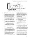
The fundamental equation relating frequency to
pressure is
P = -F
x
G + B where
P = pressure, PSI
G = the Gage Factor obtained from the
sensors calibration sheet in PSI/digit. The
units of a digit are Hz
2
(10
-3
).
B = offset
F
x
= f
2
Hz
2
(10
-3
), where f is frequency.
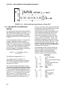
Instruction 28 measures period, T, of the
vibrating wire in milliseconds (ms) and returns a
measured value, X, of
X = 1/(T
2
(ms)
2
) = f
2
(10
-6
)Hz
2
A multiplier of -1000 in Instruction 28 converts
the measurement to digits, as shown below.
-F
x
= -X(-10
3
) = -f
2
(10
-3
)Hz
2
To calculate the multiplier, convert Geokon's
gage factor, G, to the desired units (i.e., feet of
water per digit) and multiply by -1000.
TEMPERATURE CORRECTION
The temperature correction is applied as
follows.
P
T
= P + C * (t
1
- t
0
), where
P
T
= Pressure corrected for temperature, °C
C = Temperature coefficient, PSI/°C (from
Geokon calibration sheet)
t
0
& t
1
= Initial and current temperatures, °C.
The temperature coefficient, C, must be
converted to units compatible with the gage
factor, G.
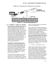
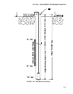
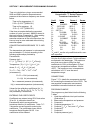
WELL MONITORING EXAMPLE
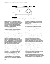
In this example the vibrating wire sensor is
used to monitor water table height (Figure 7.16-
2). The desired data is the distance from the lip
of the well to the water surface. The sensor is
vented to atmosphere to eliminate
measurement errors due to changes in
barometric pressure. The water level is
expected to stay within 40 to 80 feet of the lip
so the 50 psi pressure sensor is placed
approximately 100 feet below the lip of the well.
The calibration data from Geokon is provided in
Table 7.16-1.
TABLE 7.16-1 Calibration Data for
Sensor 3998
Gage Factor Temp. Coeff.
(psi/digit) (psi/°C)
0.0151 -0.0698
The multiplier, m, is calculated to convert the
reading to feet of water.
m = 0.0151 (psi/digit) * 2.3067 (ft of water/psi) *
-1000 = -34.831 ft of water/digit
After the probe reaches thermal equilibrium, the
initial temperature, t
0
, is measured to be 24°C.
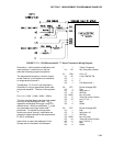
The water column above the sensor is referred
to as the "Reading". The Reading decreases
with increasing "Distance" from lip of well to
water surface so the Distance is computed by
subtracting the Reading from the Offset as
shown in Figure 7.16-2.
The "Initial Distance" to the water surface is
measured with a chalked line to be 47.23 feet
below the lip. The first time the program is
executed, the program calculates the offset
(Offset = Distance + Reading) required to
obtain a reading of 47.23 feet. The offset is
stored in Location 4 and applied to subsequent
measurements.
NOTE: Following program compilation in
the *0 Mode, all input locations are set to
zero. This fact is utilized to detect the first
execution following a program compilation.
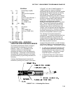
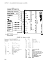
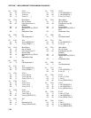
The example assumes the sensor has been
connected as shown here.