


3-1
SECTION 3. INSTRUCTION SET BASICS
The instructions used to program the CR10 are divided into four types: Input/Output (I/O), Processing,
Output Processing, and Program Control. I/O Instructions are used to make measurements and store
the readings in input locations or to initiate analog or digital port output. Processing Instructions perform
mathematical operations using data from Input Storage locations and place the results back into
specified Input Storage locations. Output Processing Instructions provide a method for generating time
or event dependent data summaries from processed sensor readings residing in specified Input Storage
locations. Program Control Instructions are used to direct program execution based on time and or
conditional tests on input data and to direct output to external devices.
Instructions are identified by a number. There are a fixed number of parameters associated with each
instruction to give the CR10 the information required to execute the instruction. The set of instructions
available in the CR10 is determined by the PROM (Programmable Read Only Memory) inside the
CR10. Appendix B lists the PROM options available.
3.1 PARAMETER DATA TYPES
There are 3 different data types used for
Instruction parameters: Floating Point (FP), 4
digit integers (4), and 2 digit integers (2). The
parameter data type is identified in the listings
of the instruction parameters in Sections 9-12.
Different data types are used to allow the CR10
to make the most efficient use of its memory.
Floating Point parameters are used to enter
numeric constants for calibrations or
mathematical operations. While it is only
possible to enter 5 digits (magnitude +.00001 to
+99999.), the internal format has a much
greater range (1x10
-19
to 9x10
18
, Section
2.2.1). Instruction 30 can be used to enter a
number in scientific notation into an input
location.
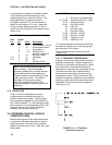
3.2 REPETITIONS
The repetitions parameter on many of the I/O,
Processing, and Output Processing Instructions
is used to repeat the instruction on a number of
sequential Input Channels or Input Storage
locations. For example, if you are making 4
differential voltage measurements on the same
voltage range, wire the inputs to sequential
channels and enter the Differential Voltage
Measurement Instruction once with 4 repetitions,
rather than entering 4 separate measurement
instructions. The instruction will make 4
measurements starting on the specified channel
number and continuing through the 3
succeeding differential channels. The results
will be stored in the specified input location and
the 3 succeeding input locations. Averages for
all 4 measurements can be calculated by
entering the Average Instruction with 4
repetitions.
When several of the same type of
measurements will be made, but the
calibrations of the sensors are different, it
requires less time to make the measurements
using one measurement with repetitions and
then apply the calibrations with a scaling array
(Inst. 53) than it does to enter the instruction
several times in order to use a different
multiplier and offset. This is due to set up and
calibration time for each measurement
instruction. However, if time is not a constraint,
separate instructions may make the program
easier to follow.
3.3 ENTERING NEGATIVE NUMBERS
After keying in a number, press C or "-" to
change the number's sign. On floating point
numbers a minus sign (-) will appear to the left
of the number. Excitation voltages in millivolts
for I/O Instructions are 4 digit integers; when C
is keyed 2 minus signs (-) will appear to the
right of the number indicating a negative
excitation. Even though this display is the
same as that indicating an indexed input
location, (Section 3.4) there is no indexing
effect on excitation voltage.
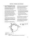
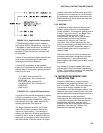
3.4 INDEXING INPUT LOCATIONS AND
PORTS
When used within a loop, the parameters for
input locations and the commands to set,
toggle, or pulse a port can be Indexed to the
loop counter. The loop counter is added to the
indexed value to determine the actual Input