


CR10 OVERVIEW
OV-7
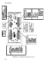
OV1.2 CONNECTING POWER TO THE CR10
The CR10 can be powered by any 12VDC
source. First connect the positive lead from the
power supply to one of the 12V terminals and
then connect the negative lead to one of the
power ground (G) terminals. The Wiring Panel
power connection is reverse polarity protected.
See Section 14 for details on power supply
connections.
CAUTION: The metal surfaces of the
CR10 Wiring Panel, and CR10KD
Keyboard Display are at the same potential
as power ground. To avoid shorting 12
volts to ground, connect the 12 volt lead
first, then connect the ground lead.
OV2. MEMORY AND PROGRAMMING
CONCEPTS
The CR10 must be programmed before it will
make any measurements. A program consists
of a group of instructions entered into a
program table. The program table is given an
execution interval which determines how
frequently that table is executed. When the
table is executed, the instructions are executed
in sequence from beginning to end. After
executing the table, the CR10 waits the
remainder of the execution interval and then
executes the table again starting at the
beginning.
The interval at which the table is executed
generally determines the interval at which the
sensors are measured. The interval at which
data are stored is separate from how often the
table is executed, and may range from samples
every execution interval to processed
summaries output hourly, daily, or on longer or
irregular intervals.
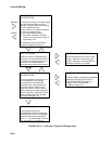
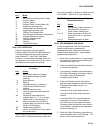
Figure OV2.1-1 represents the measurement,
processing, and data storage sequence, and
the types of instructions used to accomplish
these tasks.
OV2.1 INTERNAL MEMORY
The CR10 has 64K bytes of Random Access
Memory (RAM), divided into five areas. The
use of the Input, Intermediate, and Final
Storage in the measurement and data
processing sequence is shown in Figure
OV2.1-1. While the total size of these three
areas remains constant, memory may be
reallocated between the areas to accommodate
different measurement and processing needs
(*A Mode, Section 1.5). The size of the 2
additional memory areas, system and program,
are fixed. The five areas of RAM are:
1. Input Storage - Input Storage holds the
results of measurements or calculations.
The *6 Mode is used to view Input Storage
locations for checking current sensor
readings or calculated values. Input
Storage defaults to 28 locations. Additional
locations can be assigned using the *A
Mode (Section 1.5).
2. Intermediate Storage - Certain Processing
Instructions and most of the Output
Processing Instructions maintain
intermediate results in Intermediate
Storage. Intermediate storage is
automatically accessed by the instructions
and cannot be accessed by the user. The
default allocation is 64 locations. The
number of locations can be changed using
the *A Mode.
3. Final Storage - Final processed values are
stored here for transfer to printer, solid
state Storage Module or for retrieval via
telecommunication links. Values are stored
in Final Storage only by the Output
Processing Instructions and only when the
Output Flag is set in the users program.
Approximately 29,900 locations are
allocated to Final Storage on power up.
This number is reduced if Input or
Intermediate Storage is increased.
4. System Memory - used for overhead tasks
such as compiling programs, transferring
data etc. The user cannot access this
memory.
5. Program Memory - available for user
programs entered in program tables 1 and
2, and Subroutine Table 3.