


SECTION 12. PROGRAM CONTROL INSTRUCTIONS
12-8
The source of data is the currently active
Final Storage Area set by Instruction 80
(default = 0 or 1).NOTE: All memory
pointers are positioned 8to the DSP
location when the datalogger compiles a
program. For this reason, Always retrieve
uncollected data before making program
changes.
For example, assume the TPTR lags the DSP
by less than 512 data points when the
datalogger program is altered. On compiling,
the TPTR is positioned with the DSP, losing
reference to the data that was intended to be
transferred to tape. The data is not
automatically transferred and appears as a
discontinuity in the data file. Until the ring
memory wraps around and data overwrite
occurs, the data may be recovered using the *8
Mode. This scenario is also true for the SPTR
and data intended for a Storage Module.
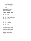
PARAM. DATA
NUMBER TYPE DESCRIPTION
01: 2 Option Device
00 = Tape
09 = Tape all data to
current DSP
80 = To the other Final
Storage Area
(New data since the
last time)
81 = The other Final
Storage Area
(The entire active Final
Storage Area)
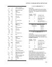
(x) BAUD RATE CODES
0 300 baud
1 1200 baud
2 9600 baud
3 76800 baud
ADDRESSED PRINT DEVICE, x = Baud code
1x = Printable ASCII
2x = Comma Delineated ASCII
3x = Binary Final Storage Format
7N = Storage Module N (N=1-8; Section 4.5.1)
7N = Output File Mark to Storage Module N
PIN-ENABLED PRINT DEVICE, x = Baud code
(SDE pulled high)
4x = Printable ASCII
5x = Comma Delineated ASCII
6x = Binary Final Storage Format
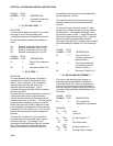
*** 97 INITIATE ***
TELECOMMUNICATIONS
Instruction 97 is used to have the CR10 initiate
telecommunications in response to certain
conditions. When the instruction is executed with
the Interrupt disable flag set low, the CR10 will
make a call and send the ID number specified in
Parameter 8 (in ASCII at the specified baud rate).
The ID number will be sent every 4 seconds until
the CR10 receives a response or the time
specified in Parameter 3 expires. The expected
response is to have the ID sent back to the
CR10, at which time the CR10 will go into the
normal telecommunications mode (Section 4)
and the time limit on the call will become inactive.
In the normal telecommunications mode, the
CR10 waits for commands from the device it
called. The CR10 will not send any data without
first receiving a command to do so. CSI's
TELCOM program (part of the PC208 Datalogger
Support Software) enables IBM PC/XT/AT/PS-2's
or compatibles to automatically answer calls and
retrieve data.
When the CR10 receives a correct character, it
restarts the 4 second timer used to determine
when the ID is sent. There is then 4 seconds in
which the CR10 waits to receive the next digit of
the ID before it again sends the ID. The CR10
must receive the ID in the correct order without
mistakes. If an incorrect character is detected,
the CR10 will immediately send the correct ID. If
a correct response is not received within the time
allotted in Parameter 3, the CR10 will hang up.
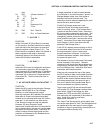
When either the RF or Hayes commands
(DC112) options are specified, the time limit on
the call (without a correct response) specified in
Parameter 3 is timed from the start of the
instruction and must include the dialing time.
If the correct response is not received, the CR10
will continue to make calls. The CR10 will repeat
the calls at the fast interval specified by Parameter
4 for the number of retries specified in Parameter
5, after which the calls will be attempted at the
slow interval specified in Parameter 6. The actual
delay between retries for both the fast and slow
attempts has a random factor built in, which is
added as an offset to the delay specified. The
random factor prevents calls from different stations
from occurring at the same time. This offset will
range between 0 and one half of the delay
specified. The resolution of the timer for these
delays is the execution interval of the table in