


SECTION 14. INSTALLATION AND MAINTENANCE
14-2
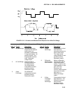
System operating time for the batteries can be
determined by dividing the battery capacity
(amp-hours) by the average system current
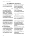
drain. The CR10 draws <1 mA in the quiescent
state, 13 mA while processing, and 46 mA
during an analog measurement; the length of
operating time for each datalogger instruction is
listed in the programming section. Typical
current requirements for common CR10
peripherals are given in Table 14.2-1.
14.3 CAMPBELL SCIENTIFIC POWER
SUPPLIES
The PS12 Power Supply is available from
Campbell Scientific with either alkaline or lead
acid batteries, the PS12ALK and PS12LA,
respectively. The PS512M is also a lead acid
supply with two 9-pin null modem ports for
communication modems, see Section 14.3.3.
The PS12ALK has 8 D cell alkaline batteries,
the PS12LA has a rechargeable lead acid
battery. The alkaline batteries are discarded
after use. The lead acid batteries should be
float charged with either AC power or a solar
panel. The lead acid battery supplies power
during a power failure or in times of low charge
with a solar panel.
The CH12R and CH512R contain the same
circuitry as the PS12LA and PS512M,
respectively. They are used to float charge an
external 12 VDC Yuasa battery using AC or
solar power. No internal batteries are
contained in the CH12R and CH512R. Their
operation, however, is identical to that of the
PS12LA and PS512M. Other power supply
options are connecting a 12 volt battery directly
to the CR10, Section 14.5, or supplying power
from a vehicle, Section 14.6.
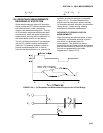
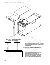
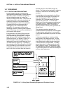
The PS12 Power Supply provides 12 volts,
regulates incoming AC or DC power, limits
current from the battery, and provides circuitry
to connect an external 12 volt battery. The
terminals on the PS12 are exposed by
unscrewing the two set screws, as shown in
Figure 4.3-1.
The two 12 volt and two ground terminals are
for supplying power to the datalogger, or other
12 volt devices.
The two terminals, labeled CHG, are for
connecting a 20 VDC adapter or solar panel to
charge lead acid batteries.
The charge input can be either AC or DC, and it
does not matter which terminal is positive or
negative. The voltage input must be within 16
to 26 VDC, or 16 to 26 VAC RMS.
The ON-OFF switch controls power to the 12 V
ports. Charging of lead acid batteries still
occurs when the switch is off. The red charge
light is on when a charging source is connected
to the power supply.
The connectors labeled INT and EXT are for
connecting the internal (power supply) battery
and an external battery, respectively. A five
foot cable, with connector, is included with the
power supply for connection to an external
battery. This is commonly used for supplying
power to the datalogger while changing power
supply batteries.
A thermal fuse in the power circuit limits source
current. If excessive current is drawn, the fuse
gets hot, increases in resistance, and limits
current. When the problem is fixed, the fuse
cools and the resistance decreases, eventually
allowing current to pass. When excessive
current is drawn due to shorting the power
leads to the Wiring Panel, allow 10 to 15
seconds for the fuse to cool before connecting
power.
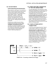
14.3.1 PS12ALK ALKALINE POWER SUPPLY
The PS12ALK utilizes 8 alkaline D cells
mounted in place of the lead acid battery shown
in Figure 14.3-1. The PS12ALK can also be
used with a lead acid battery connected to the
external battery port, in this case the alkaline
batteries act as a backup.
Before installing the alkaline batteries, connect
all necessary sensor leads, control lines, and
power leads. The CR10 can be turned on and
off with the switch on the PS12ALK.
To replace the batteries without losing the
datalogger program and data: 1) do not turn the
power switch off, 2) connect an external battery
to the port labeled EXT with the supplied 6 foot
cable, 3) remove the old batteries, 4) replace
with new alkaline D cell batteries, and 5)
remove the external battery.
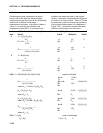
A fresh set of eight alkaline D cells has 12.4
volts and a nominal rating of 7.5 amp-hours at
20°C. The amp-hour rating decreases with
temperature as shown in Table 14.3-1.
Datalogger Instruction 10 can be used to