


SECTION 1. FUNCTIONAL MODES
1-6
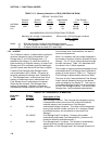
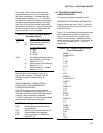
TABLE 1.5-1. Memory Allocation in CR10 (32K ROM, 64K RAM)
DEFAULT ALLOCATION
Program System Input Intermediate Final Storage
Memory Memory Storage Storage Area 1 Area 2
64K RAM
Bytes 1986 3302 112 256 59,816 0
Loc. 28 64 29,908 0
MAXIMUM REALLOCATION FROM FINAL STORAGE
Maximum No. of Input + Intermediate Minimum No. of Final Storage Locations
Storage Locations Area 1 + Area 2
6,862 16,368
Notes: 1) 28 is the minimum number of Input Storage locations.
2) 768 is the minimum number of Final Storage Area 1 locations.
3) 64 bytes of RAM are not used (32 in each chip).
1.5.2 *A MODE
The *A Mode is used to 1) determine the number of
locations allocated to Input, Intermediate, Final
Storage Area 2, and Final Storage Area 1; 2)
repartition this memory; 3) check the number of
bytes remaining in Program memory; 4) erase Final
Storage; and 5) to completely reset the datalogger
(just as if power were turned off and then on again).
A second Final Storage area (Storage Area 2)
can be allocated in the *A Mode. On power up,
locations allocated for Storage Area 2 defaults to
0. Final Storage Area 1 is the source from which
memory is taken when Input, Intermediate, and
Final Storage Area 2 memories are increased.
When they are reduced, Final Storage Area 1
memory is increased. Allocation of Input and
Intermediate Storage locations does NOT change
Final Storage Area 2 and therefore, the data in
this area are preserved.
When *A is entered, the first number displayed is
the number of memory locations allocated to Input
Storage. The "A" key is used to advance through
the next 4 windows. Table 1.5-2 describes what
the values in the *A Mode represent.
The number of memory locations allocated to Input,
Intermediate and Final Storage Area 2 defaults at
power-up to the values in Table 1.5-1. The size of
Final Storage is determined by the size of RAM.
The sizes of Input, Intermediate and Final Storage
Area 2 may be altered by keying in the desired
value and entering it by keying "A". One Input or
Intermediate Storage location can be exchanged
for two Final Storage locations. The size of Final
Storage Area 1 will be adjusted automatically.
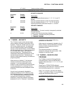
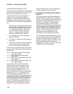
TABLE 1.5-2. Description of *A Mode Data
Keyboard Display
Entry ID: Data
Description of Data
*A 01: XXXX Input Storage Locations. This value can be changed by keying
in the desired number (minimum of 28, maximum limited by
available memory and constraints on Final Storage).
A 02: XXXX Intermediate Storage Locations. This value can be changed by
keying in the desired number (minimum of 0, maximum limited
by available memory and constraints on Input and Final
Storage).
A 03: XXXXX Final Storage Area 2 Locations. Changing this number
automatically reallocates Final Storage Area 1 (minimum of 0,
maximum limited by available memory.)
A 04: XXXXX Final Storage Area 1 Locations. This number is automatically
altered when the number of memory locations in Input,
Intermediate, or Final Storage Area 2 are changed (minimum of
768).