


G-1
APPENDIX G. CHANGING RAM OR PROM CHIPS
The CR10 has two sockets for Random Access
Memory (RAM) and one socket for
Programmable Read Only Memory (PROM).
The standard CR10 has 64K of RAM, (a 32K
RAM chip in each socket). Earlier CR10s had
16K of RAM (an 8K RAM chip in each socket).
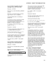
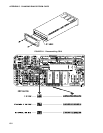
G.1 DISASSEMBLING THE CR10
The sockets provided for RAM and PROM are
located on the CR10 CPU circuit card inside the
CR10 can. To expose the RAM and PROM
sockets, remove the two phillips head screws
from the end opposite the connectors. Remove
the end cap. The ends of two circuit cards and
the RF shield will be visible (see Figure G-1).
Now lay the CR10 on a flat surface, (i.e., a
table), and push on the RF shield with your
thumbs while grasping the can with your hands.
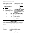
Remove the circuit cards from the can. Orient
the cards with the connector on the left and with
the card that matches Figure G-2. The Central
Processing Unit (CPU) is found at location H-9
and the three slots for RAM and PROM will be
directly beneath it.
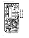
G.2 INSTALLING NEW RAM CHIPS IN
CR10s WITH 16K RAM
The two 8K RAM chips are found at locations
C-11 and C-14. With a small flat screw driver
gently pry out the two 8K RAM chips at these
locations and replace them with the 32K RAM
chips provided in the memory upgrade. The
new chips should be installed so the notched
end is towards the nearest card edge. Before
pushing the chips into the socket make certain
that all the pins are correctly seated. After
installing the 32K chips check for pins that may
be bent or not firmly seated in the socket. If
you notice a bent pin, remove the chip, carefully
straighten it and repeat the installation
procedure.
G.2.1 CHANGING JUMPERS
There are six jumpers used to configure
hardware for different RAM sizes. Figure 2
shows the jumper settings for different memory
configurations. A pin or small screw driver tip
will work best for pulling these jumpers and
relocating them as shown in Figure 2.
G.2.2 RAM TEST
Attach the CR10KD Keyboard/Display and
apply power to the CR10. After the CR10
executes the RAM/PROM self test, the number
96 should be displayed in the window. The
number is the sum of Kbytes in RAM (64) plus
the number of Kbytes in ROM (32).
G.3 INSTALLING NEW PROM
The PROM chip is found at location C8 on the
CR10 CPU board, (see Figure G-2). With a
small flat screw driver, gently pry out the PROM
chip and replace it with the new one. The new
chip should be installed so that the notched end
is towards the nearest card edge. Before
pushing the chip into the socket make certain
that all the pins are seating correctly. After
installing the chip check for pins that may be
bent or not making contact. If you notice a bent
pin, remove the chip, carefully straighten it and
repeat the installation procedure.
To make certain that the new chip is installed
correctly enter the CR10 *B mode, (Section
1.6), and advance to the second window. This
window displays the PROM signature. The five
digit number in the window should match the
PROM signature given with the new PROM
documentation. If the numbers are different
disassemble the CR10 and look for pins that
are bent or not firmly seated.
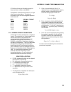
G.4 INSTALLING 4K PROGRAM
MEMORY PROM
Newer CR10s (shipped after 11-4-93) can be
converted from the standard 2K Program
Memory to 4K Program Memory by installing
the correct PROM and moving a jumper.
Figure G-3 shows the location and settings for
the jumper. Install the PROM as described in
Section G.3.
Older CR10s do not have this jumper and must
be sent to Campbell Scientific for a hardware
modification to 4K Program Memory.