


SECTION 13. CR10 MEASUREMENTS
13-22
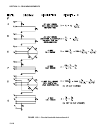
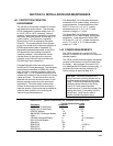
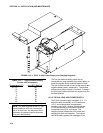
FIGURE 13.6-2. Model of Resistive Sensor with Ground Loop
In Figure 13.6-2, V
x
is the excitation voltage, R
f
is a fixed resistor, R
s
is the sensor resistance,
and R
G
is the resistance between the excited
electrode and CR10 earth ground. With R
G
in
the network, the measured signal is:
R
s
V
1
= V
x
__________________ [13.6-1]
(R
s
+R
f
) + R
s
R
f
/R
G
R
s
R
f
/R
G
is the source of error due to the
ground loop. When R
G
is large the equation
reduces to the ideal. The geometry of the
electrodes has a great effect on the magnitude
of this error. The Delmhorst gypsum block
used in the 227 probe has two concentric
cylindrical electrodes. The center electrode is
used for excitation; because it is encircled by
the ground electrode, the path for a ground loop
through the soil is greatly reduced. Moisture
blocks which consist of two parallel plate
electrodes are particularly susceptible to
ground loop problems. Similar considerations
apply to the geometry of the electrodes in water
conductivity sensors.
The ground electrode of the conductivity or soil
moisture probe and the CR10 earth ground
form a galvanic cell, with the water/soil solution
acting as the electrolyte. If current was allowed
to flow, the resulting oxidation or reduction
would soon damage the electrode, just as if DC
excitation was used to make the measurement.
Campbell Scientific probes are built with series
capacitors in the leads to block this DC current.
In addition to preventing sensor deterioration,
the capacitors block any DC component from
affecting the measurement.
13.7 CALIBRATION PROCESS
The CR10 makes voltage measurements by
integrating the input signal for a fixed time and
then holding the integrated value for the analog
to digital (A/D) conversion. The A/D conversion
is made by a 13 bit approximation using a
digital to analog converter (DAC). The result
from the approximation is DAC counts, which
are multiplied by coefficients to obtain millivolts
(mV). There are 10 calibration coefficients, one
for each of the 5 gain ranges for the fast and
slow integration times.
The CR10 has an internal calibration function
that feeds positive and negative voltages
through the amplifiers and integrator and
calculates new calibration coefficients. By
adjusting the calibration coefficients the
accuracy of the voltage measurements is
maintained over the -25 to +50°C operating
range of the CR10. Calibration is executed
under four conditions:
1. When the CR10 is powered up.
2. Automatically when Instruction 24 is not
contained in a program table.
3. When the watchdog resets the processor.
4. When the calibration instruction, Instruction
24, is executed.
AUTOMATIC CALIBRATION SEQUENCE
The primary advantage of automatic calibration
is that the CR10 is constantly calibrated without
user programming. The CR10 defaults to
automatic calibration when Instruction 24 is not
contained in a program table.
Every 8 seconds one part of a 22 part
calibration sequence is performed. Program
execution is interrupted (5.4 - 21.4 ms), when
necessary, for each part of the calibration.
Every 2.9 minutes (8 seconds * 22) ten
calibration coefficients are calculated. The
calculated coefficients are multiplied by 1/5,
and then added to 4/5 times the existing
coefficients. Averaging is done as a safeguard
against coefficients calculated from a noisy
measurement.
The above weighting of the newly calculated
coefficients results in a 15 minute time constant
(see Instruction 58) in the response of the
calibration to step changes affecting the
calibration coefficients (primarily temperature).
For most environmental applications a 15
minute time constant is acceptable. The
automatic calibration may result in the
calibration coefficients not being optimum for
applications that subject the CR10 to extreme
temperature gradients.
Automatic calibration extends the processing
time 5.4 to 21.4 ms when it is executed (every 8