SECTION 4. EXTERNAL STORAGE PERIPHERALS
4-8
Module is connected, and it is not full, address
1 will address that Storage Module regardless
of the address that is assigned to the Module.
Address 1 would be used with Instruction 96 if
several Storage Modules with different
addresses were connected to the CR10 and
were to be filled sequentially. The Storage
modules would be configured as fill and stop.
When the lowest addressed Module was full
data would be written to the next lowest
addressed Module, etc.
4.5.2 STORAGE MODULE USE WITH
INSTRUCTION 96
When output to the Storage Module is enabled
with Instruction 96, the Storage Module(s) (see
4.5.1 for addressing on multiple modules) may
be either left with the CR10 for on-line data
transfer and periodically exchanged, or brought
to the site for data transfer.
USE OF STORAGE MODULE TO PICK UP DATA
The CR10 is capable of recognizing whether or
not the Storage Module is connected. Each
time Instruction 96 is executed and there is
data to output, the CR10 checks for the
presence of the Storage Modules. If one is not
present, the CR10 does not attempt to output
data to it. Instead, the CR10 saves the data
and continues its other operations without
advancing the Storage Module Pointer (SPTR,
Section 2.1).
When the user finally does connect the Storage
Module to the CR10, two things happen:
1. Immediately upon connection, a File Mark is
placed in the Storage Module Memory
following the last data stored (if a File Mark
wasn't the last data point already in storage).
2. During the next execution of Instruction 96,
the CR10 recognizes that the Storage
Module (SM) is present and outputs all data
between the SPTR and the DSP location.
The File Mark allows the operator to distinguish
blocks of data from different dataloggers or
from different visits to the field.
To be certain that the SM has been connected
to the CR10 during an execution of P96, the
user can:
• Leave the SM connected for a time period
longer than an execution interval OR
• Use the SC90 9-Pin Serial Line Monitor. The
SC90 contains an LED which lights up during
data transmission. The user connects the SM
to the CR10 with the SC90 on the line and
waits for the LED to light. When the light goes
off, data transfer is complete and the SM can
be disconnected from the CR10.
4.5.3 *8 DUMP TO STORAGE MODULE
In addition to the on-line data output
procedures described above, output from CR10
Final Storage to the SM192 and SM716 can be
manually initiated in the *8 Mode. The
procedure for setting up and transferring data is
as follows:
1. Connect the CR10KD Keyboard/Display (or
terminal) and the Storage Module in parallel
to the CR10 using the SC12 cable. For
terminals, an SC32A will be needed. See
Section 5 for interfacing details.
2. Key in the appropriate commands as listed
in Table 4.2-1.
4.6 *9 MODE -- STORAGE MODULE
COMMANDS
The *9 Mode is used to issue commands to the
Storage Module (from the CR10) using the
CR10KD or a terminal/computer. These
"commands" are like * Modes for the Storage
Module and in some cases are directly analogous
to the CR10 * Modes. Command 7 enters a mode
used to review stored data, and 8 is used to
transfer data between two Storage Modules
connected to the CR10. The operations with the
Storage Module are not directly analogous as may
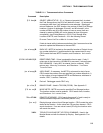
be seen in Table 4.6-1 which lists the commands
(e.g., when reviewing data, #A advances to the
start of the next Output Array rather than to the
same element in the next array with the same ID).
When *9 is keyed, the CR10 responds: 09:01
1 is the default address for the Storage Module
(Section 4.4.1). If you have more than 1
Storage Module connected, enter the address
of the desired Storage Module. Address 1 will
always work if only one Module is connected.
Key A and the CR10 responds: 9N:00
Where N is the address which was entered.
You may now enter any of the commands in
Table 4.6-1 (key in the command number and
enter with A). Most commands have at least


