


SECTION 1. FUNCTIONAL MODES
1-4
1.3.2 DISPLAYING AND TOGGLING USER FLAGS
If D is keyed while the CR10 is displaying a
location value, the current status of the user flags
will be displayed in the following format:
"00:010010". The characters represent the flags,
the left-most digit is Flag 1 and right most is Flag
8. A "0" indicates the flag is clear and a "1"
indicates the flag is set. In the above example,
Flags 4 and 7 are set. To toggle a flag, simply
press the corresponding number. To return to
displaying the input location, press "A".
Entering appropriate flag tests into the program
allows manual control of program execution.
For example, to manually start the execution of
Table 2: enter Instruction 91 as the first
instruction in Table 2. The first parameter is 25
(do if Flag 5 is low), the second parameter is 0,
go to end of program table. If Flag 5 is low, all
subsequent instructions in Table 2 will be
skipped. Flag 5 can be toggled from the *6
Mode, effectively starting and stopping the
execution of Table 2.
1.3.3 DISPLAYING AND TOGGLING PORTS
The current status of the user's ports can be
displayed by hitting "0" while looking at an input
location (e.g., *6A0). Ports are displayed left to
right as C8, C7, ... , C1 (exactly opposite to the
flags). A port configured as output can be
toggled by hitting its number while in the port
display mode. There is no effect on ports
configured as inputs.
On power up all ports are configured as inputs.
Instruction 20 is used to configure a port as an
output. Ports are also configured as outputs by
any program control commands which uses the
port as an output (pulse, set high, set low,
toggle).
1.4 COMPILING AND LOGGING DATA -
*0 MODE
When the *0 Mode is entered after
programming the CR10, a program compile
function is executed and the display shows
"LOG" followed by the program table numbers
that were enabled at compilation time. The
display is not updated after entering *0.
NOTE: All output ports are set low, the
timer is reset, and data values in Input and
Intermediate Storage are RESET TO ZERO
whenever the program tables are altered
and the Program is recompiled with the *0
Mode. The same is true when the
programs are compiled with *B or *D.
To minimize current drain, the CR10 should be
left in the *0 Mode when logging data.
1.5 MEMORY ALLOCATION - *A
1.5.1 INTERNAL MEMORY
There are 2 sockets for Random Access Memory
(RAM) and 1 socket which is used for
(Programmable) Read Only Memory (PROM).
The standard CR10 has 64K of RAM: a 32K RAM
chip in each socket. Earlier versions had an 8K
RAM chip in each socket. Appendix G describes
how to change RAM and PROM chips.
When powered up with the keyboard display
attached, the CR10KD displays HELLO while
performing a self check. The total system
(RAM and ROM) memory is then displayed in K
bytes. The size of RAM can be displayed in the
*A mode.
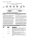
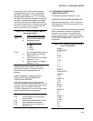
There are 1986 bytes allotted to Program
memory. This memory may be used for 1 table
or shared among all tables. Tables 3.9-1 to
3.9-4 list the amount of memory used by
program instructions.
Input Storage is used to store the results of
Input/Output and Processing Instructions. The
values stored in input locations may be
displayed using the *6 Mode (Section 1.3).
The results of Output Instructions (data used for
a permanent record) are stored in Final Storage
when the Output Flag is set (Section 3.7). The
data in Final Storage can be monitored using
the *7 Mode (Section 2.3).
Intermediate Storage is a scratch pad for
Output Processing Instructions. It is used to
store the results of intermediate calculations
necessary for averages, standard deviations,
histograms, etc. Intermediate Storage is not
accessible by the user.
Each Input or Intermediate Storage location
requires 4 bytes of memory. Each Final
Storage location requires 2 bytes of memory.
Low resolution data points require 1 Final
Storage location and high resolution data points