


CR10 OVERVIEW
OV-10
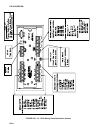
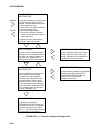
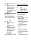
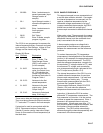
Table 1.
Execute every x sec.
0.0156 < x < 8191
Instructions are executed
sequentially in the order they
are entered in the table.
One complete pass through
the table is made each
execution interval unless
program control instructions
are used to loop or branch
execution.
Normal Order:
MEASURE
PROCESS
CHECK OUTPUT COND.
OUTPUT PROCESSING
Table 2.
Execute every y sec.
0.0156 < y < 8191
Table 2 is used if there is a
need to measure and
process data on a separate
interval from that in Table 1.
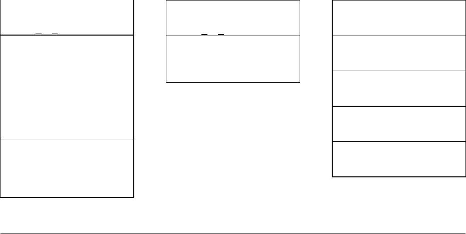
Table 3.
Subroutines
A subroutine is executed
only when called from Table
1 or 2.
Subroutine Label
Instructions
End
Subroutine Label
Instructions
End
Subroutine Label
Instructions
End
FIGURE OV2.3-1. Program and Subroutine Tables
Each instruction in the table requires a finite
time to execute. If the execution interval is less
than the time required to process the table, an
execution interval overrun occurs; the CR10
finishes processing the table and waits for the
next execution interval before initiating the
table. When an overrun occurs, decimal points
are shown on either side of the G on the display
in the LOG mode (*0). Overruns and table
priority are discussed in Section 1.1.
OV2.3.2. THE OUTPUT INTERVAL
The interval at which output occurs is
independent from the execution interval, other
than the fact that it must occur when the table is
executed (e.g., a table cannot have a 10 minute
execution interval and output every 15
minutes).
A single program table can have many different
output intervals and conditions, each with a
unique data set (Output Array). Program
Control Instructions are used to set the Output
Flag. The Output Processing Instructions
which follow the instruction setting the Output
Flag determine the data output and its
sequence. Each additional Output Array is
created by another Program Control Instruction
checking a output condition, followed by Output
Processing Instructions defining the data set to
output.
OV3. COMMUNICATING WITH CR10
An external device must be connected to the
CR10's Serial I/O port to communicate with the
CR10. This may be either Campbell Scientific's
portable CR10KD Keyboard Display or a
computer/terminal.
The CR10KD is powered by the CR10 and
connects directly to the serial port via the SC12
cable (supplied with the CR10KD). No
interfacing software is required.
To communicate with any device other than the
CR10KD, the CR10 enters its Telecom-
munications Mode and responds only to valid
telecommunications commands. Within the
Telecommunications Mode, there are 2 "states";
the Telecommunications Command state and the
Remote Keyboard state. Communication is
established in the Telecommunications command
state. One of the commands is to enter the
Remote Keyboard state.
The Remote Keyboard state allows the
keyboard of the computer/terminal to act like
the CR10KD keyboard. Various datalogger
modes may be entered, including the mode in
which programs may be keyed in to the CR10
from the computer/terminal.
Campbell Scientific's PC208 Datalogger
Support Software facilitates the use of IBM
PC/XT/AT/PS-2's and compatibles for
communicating with the CR10. This package