


SECTION 7. MEASUREMENT PROGRAMMING EXAMPLES
7-24
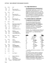
23: P30 Z=F
01: 0 F
02: 0 Exponent of 10
03: 40 Z Loc [:SCRATCH 1]
24: P30 Z=F
01: 0 F
02: 0 Exponent of 10
03: 41 Z Loc [:SCRATCH 2]
25: P30 Z=F
01: 0 F
02: 0 Exponent of 10
03: 42 Z Loc [:CMPILE CK]
26: P95 End
27: P85 Beginning of Subroutine
01: 2 Subroutine Number
28: P 36 Z=X*Y
01: 15 X Loc POLLY M4
02: 8 Y Loc U
03: 40 Z Loc [:SCRATCH 1]
29: P33 Z=X+Y
01: 16 X Loc POLY M3
02: 40 Y Loc SCRATCH 1
03: 40 Z Loc [:SCRATCH 1]
30: P87 Beginning of Loop
01: 0 Delay
02: 3 Loop Count
31: P36 Z=X*Y
01: 8 X Loc U
02: 40 Y Loc SCRATCH 1
03: 40 Z Loc [:SCRATCH 1]
32: P33 Z=X+Y
01: 17-- X Loc POLY M2
02: 40 Y Loc SCRATCH 1
03: 40 Z Loc [:SCRATCH 1]
33: P95 End
34: P95 End
35: P End Table 3
* A Mode 10 Memory
Allocation
01: 50 Input locations
02: 64 Intermediate locations
03: 0.0000 Final Storage Area 2
7.18 SDM PERIPHERALS
The SDM peripherals are measurement and
control modules which are controlled by the
CR10 through control ports 1, 2, and 3. The
instructions for these peripherals are: 101
SDM-INT8 8 channel interval timer, 102 SDM-
SW8 8 channel switch closure multiplexer, 103
SDM-A04 4 channel analog output multiplexer,
and 104 SDM-CD16 16 channel control port
expansion. Please consult the SDM peripheral
manual for programming examples.
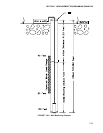
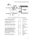
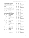
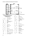
7.19 PAROSCIENTIFIC PRESSURE
TRANSDUCER PROCESSING
This example demonstrates the use of
Instruction 64 and 65 for calculating the
pressure measured with a Paroscientific "T"
Series transducer. Figure 7.17-1 details the
components required for connecting the
transducer to the CR10. The user-supplied
components are commonly available at
commercial electronic stores.
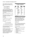
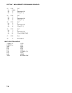
Example: The 14 coefficients shown below are
for Paroscientific "T" Series transducer Serial
Number 30135. Your coefficients will be
different.
Coeff. Value Entry
U
0
5.860253 5.8603
Y
1
-3970.348 -3970.3
Y
2
-7114.265 -7114.3
* Y
3
102779.1 102.78
C
1
70.29398 70.294
C
2
6.610141 6.6101
C
3
-119.2867 -119.29
* D
1
0.0308837 30.884
D
2
0.0 0.0
T
1
26.33703 26.337
T
2
0.8516985 0.85170
T
3
21.80118 21.801
T
4
0.0 0.0
T
5
0.0 0.0
* Y
3
and D
1
coefficients are entered as Y
3
/1000
and D
1
*1000.
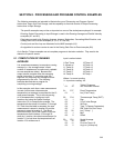
The following example reads the coefficients
from a subroutine only when the datalogger
program is compiled. The coefficients are
stored in Input Locations 3 through 16. The
temperature frequency is read on single-ended
Channel 12 and stored in Input Location 1.
Pressure is measured on single-ended Channel
1 and stored in Location 2. Instruction 64