


CR10 OVERVIEW
OV-8
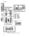
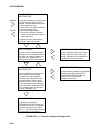
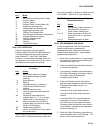
INPUT/OUTPUT
INSTRUCTIONS
Specify the conversion of a sensor signal
to a data value and store it in Input
Storage. Programmable entries specify:
(1) the measurement type
(2) the number of channels to measure
(3) the input voltage range
(4) the Input Storage Location
(5) the sensor calibration constants
used to convert the sensor output to
engineering units
I/O Instructions also control analog
outputs and digital control ports.
INPUT STORAGE
Holds the results of measurements or
calculations in user specified locations.
The value in a location is written over
each time a new measurement or
calculation stores data to the locations.
OUTPUT PROCESSING
INSTRUCTIONS
Perform calculations over time on the
values updated in Input Storage.
Summaries for Final Storage are
generated when a Program Control
Instruction sets the Output Flag in
response to time or events. Results
may be redirected to Input Storage for
further processing. Examples include
sums, averages, max/min, standard
deviation, histograms, etc.
Output Flag set high
FINAL STORAGE
Final results from OUTPUT
PROCESSING INSTRUCTIONS are
stored here for on-line or interrogated
transfer to external devices (Figure
OV5.1-1). The newest data are stored
over the oldest in a ring memory.
PROCESSING INSTRUCTIONS
Perform calculations with values in Input
Storage. Results are returned to Input
Storage. Arithmetic, transcendental and
polynomial functions are included.
INTERMEDIATE STORAGE
Provides temporary storage for intermediate
calculations required by the OUTPUT
PROCESSING INSTRUCTIONS; for
example, sums, cross products,
comparative values, etc.
FIGURE OV2.1-1. Instruction Types and Storage Areas
Control
Sensors