


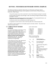

SECTION 8. PROCESSING AND PROGRAM CONTROL EXAMPLES
8-6
situation, it is more likely that the pulse
counters would be used for 2 wind speeds.) In
Program Table 1, the 2 normal pulse inputs are
read and the hourly totals output to Final
Storage with Instruction 72.
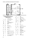
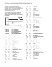
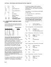
The rain gage is connected as diagrammed
below. When the switch closes, 5 volts is
applied to port 8 which causes the subroutine to
be executed.
FIGURE 8.5-1. Connections for Rain Gage
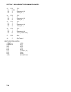
Input location Assignments:
10:Rain #1 (from Pulse count)
11:Rain #2 (from Pulse count)
12:Rain #3 (from subroutine 98 while
Output Flag is low)
13:Rain alt (from subroutine 98 while
Output Flag is high)
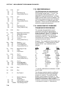
* 1 Table 1 Programs
01: 10 Sec. Execution Interval
01: P3 Pulse
01: 2 Reps
02: 1 Pulse Input Chan
03: 2 Switch Closure
04: 10 Loc [:Rain #1 ]
05: .254 Mult
06: 0 Offset
02: P92 If time is
01: 0 minutes into a
02: 60 minute interval
03: 10 Set high Flag 0 (output)
03: P77 Real Time
01: 110 Day,Hour-Minute
04: P 72 Totalize
01: 2 Reps
02: 10 Loc Rain #1
05: P91 If Flag/Port
01: 10 Do if flag 0 (output) is high
02: 30 Then Do
06: P70 Sample
01: 1 Reps
02: 12 Loc Rain #3
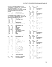
07: P30 Z=F
01: 0 F
02: 0 Exponent of 10
03: 12 Z Loc [:Rain #3 ]
08: P86 Do
01: 20 Set low Flag 0 (output)
09: P33 Z=X+Y
01: 13 X Loc Rain alt
02: 12 Y Loc Rain #3
03: 12 Z Loc [:Rain #3 ]
10: P30 Z=F
01: 0 F
02: 0 Exponent of 10
03: 13 Z Loc [:Rain alt ]
11: P95 End
12: P End Table 1
* 3 Table 3 Subroutines
01: P85 Beginning of Subroutine
01: 98 Subroutine Number
02: P91 If Flag/Port
01: 10 Do if flag 0 (output) is high
02: 30 Then Do
03: P34 Z=X+F
01: 13 X Loc Rain alt
02: 0.254 F
03: 13 Z Loc [:Rain alt ]
04: P94 Else
05: P34 Z=X+F
01: 12 X Loc Rain #3
02: .254 F
03: 12 Z Loc [:Rain #3 ]
06: P95 End
07: P22 Excitation with Delay
01: 1 EX Chan
02: 0 Delay w/EX (units=.01sec)
03: 20 Delay after EX
(units=.01sec)
04: 0 mV Excitation
08: P95 End
09: P End Table 3