


SECTION 9. INPUT/OUTPUT INSTRUCTIONS
9-12
general purpose data reduction program also
contained in PC208.
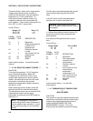
If SPLIT is not available for converting the raw
A/D, the following A/D format information is
provided for decoding purposes. At the start of
the series of measurements, the CR10 makes a
self-calibration measurement. The calibration
data is sent at the start of the measurement
data. The serial data is sent as a series of
signed 2 byte integers (most significant byte
sent first; i.e., Integer = 256 * byte 1 + byte 2):
I1...In. The first integer, I1 is a start of output
identifier, FCxx (hex), where the first byte is
always FC (never seen in the data), and the
second byte is a number less than 100
(decimal, 64 hex), which is the Instruction
Location Number of Instruction 23 in the
program table. I2 divided by I3 is the multiplier
and I4 the offset (to the raw data) determined
by the first calibration. I2 is a fixed value
determined by the input range selected. I5
through In are the raw measurement data.
Thus, the value of the first measurement sent
(M1) in millivolts is:
M
1
= I
2
/I
3
(I
5
- I
4
)
The measurement data are sent in the order
that the measurements are made (i.e., the first
measurement for each channel, then the
second measurement for each channel, etc.).
NOTE: When the raw serial data option is
selected, the calibration values are for
conversion to millivolts only. Parameters
11 and 12 are ignored.
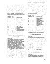
SCAN INTERVAL
Instruction 23 has its own scan interval
independent of the execution interval of the
program table in which it resides. The
resolution of the clock timing the execution
interval is 813 nanoseconds. This scan
interval, entered in Parameter 5 (in
milliseconds), is the time between each scan of
the specified channels (i.e., if 4 channels are
specified in Parameter 1, and the scan interval
is 5 ms, then the 4 measurements will be
repeated every 5 ms). The minimum time that
is allowed per measurement is 1.333 ms. The
maximum time that is allowed per
measurement is 50 ms. If the scan interval
entered does not allow this much time per
measurement (e.g., if with 4 reps, an interval
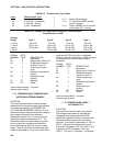
less than 5.332 ms is entered), an error code, E
61, will be displayed when the program is
compiled. When sending data to the serial port,
the rate at which the data can be transferred
may limit the scan interval (e.g., at 9600 baud
the minimum time per measurement is 2.2 ms).
Burst/Telecommunications Considerations
If a Burst measurement sequence is in
progress, raising the datalogger's ring line will
abort the Burst sequence. Peripherals which
raise the ring line are modems (i.e., RF,
Telephone, Short Haul, MD9, SC32A) or the
CR10KD.
If the Burst Measurement Instruction is
encountered while telecommunications is in
progress, the destination of the data determines
whether or not the instruction is executed:
Burst data sent to input locations
If a CR10 already in Telecommunications mode
executes a Burst instruction specifying that
Burst data be sent to input locations, all
telecommunication activity will be suspended.
After the Burst trigger condition is met and all
Burst measurements made,
telecommunications activity can resume.
Burst data sent to Serial I/O Port
If the Burst instruction specifies that Burst data
be sent to the serial port (i.e., Storage Module),
CR10 program execution will pause until the
Telecommunication mode is exited. During this
pause telecommunications (i.e., view input
locations, Monitor Mode with Term, etc.) can
continue. No Burst measurements are made
while in telecommunications and no Burst data
is sent to the serial port. After
telecommunications has ended, datalogger
program execution will resume as if the Burst
instruction were just executed.
NOTE: Instruction 23 can be aborted by
pressing any key on the CR10KD Keyboard
Display.
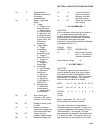
PARAM. DATA
NUMBER TYPE DESCRIPTION
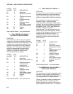
01: 2 Repetitions (no. of
channels)
02: 2 Range code (13-15)