


SECTION 13. CR10 MEASUREMENTS
13-15
temperature due to the voltage measurements
is a few hundredths of a degree.
THERMOCOUPLE POLYNOMIALS - Voltage
to Temperature Conversion
NBS Monograph 125 gives high order
polynomials for computing the output voltage of a
given thermocouple type over a broad range of
temperatures. In order to speed processing and
accommodate the CR10's math and storage
capabilities, 4 separate 6th order polynomials are
used to convert from volts to temperature over
the range covered by each thermocouple type.
Table 13.4-2 gives error limits for the
thermocouple linearization functions.
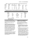
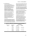
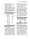
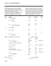
TABLE 13.4-2. Limits of Error on CR10
Thermocouple Output Linearization
(Relative to NBS Standards)
TC Type Range °C Limits of Error °C
T -270 to 400
-270 to -200 ±18 @ -270
-200 to -100 ± 0.08
-100 to 100 ± 0.001
100 to 400 ± 0.015
J -150 to 760 ± 0.008
-100 to 300 ± 0.002
E -240 to 1000
-240 to -130 ± 0.4
-130 to 200 ± 0.005
200 to 1000 ± 0.02
K -50 to 1372
-50 to 950 ± 0.01
950 to 1372 ± 0.04
REFERENCE JUNCTION COMPENSATION -
Temperature to Voltage
The polynomials used for reference junction
compensation (converting reference temperature
to equivalent TC output voltage) do not cover the
entire thermocouple range. Substantial errors
will result if the reference junction temperature is
outside of the calibrated range. The ranges
covered by these calibrations include the CR10
environmental operating range, so there is no
problem when the CR10 is used as the reference
junction. External reference junction boxes,
however, must also be within these temperature
ranges. Temperature difference measurements
made outside of the reference temperature range
should be made by obtaining the actual
temperatures referenced to a junction within the
reference temperature range and subtracting.
Table 13.4-3 gives the reference temperature
ranges covered and the limits of error in the
linearizations within these ranges.
Two sources of error arise when the reference
temperature is out of range. The most significant
error is in the calculated compensation voltage;
however, error is also created in the temperature
difference calculated from the thermocouple
output. For example, suppose the reference
temperature for a measurement on a type T
thermocouple is 300°C. The compensation
voltage calculated by the CR10 corresponds to a
temperature of 272.6°C, a -27.4°C error. The
type T thermocouple with the measuring junction
at 290°C and reference at 300°C would output -
578.7 µV; using the reference temperature of
272.6°C, the CR10 calculates a temperature
difference of -10.2°C, a -0.2°C error. The
temperature calculated by the CR10 would be
262.4°C, 27.6°C low.
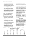
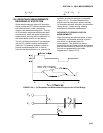
TABLE 13.4-3. Reference Temperature
Compensation Range and Linearization
Error Relative to NBS Standards
TC Type Range °C Limits of Error °C
T -100 to 100 ± 0.001
J -150 to 296 ± 0.005
E -150 to 206 ± 0.005
K -50 to 100 ± 0.01
ERROR SUMMARY
The magnitude of the errors described in the
previous sections illustrate that the greatest
sources of error in a thermocouple temperature
measurement are likely to be due to the limits of
error on the thermocouple wire and in the reference
temperature determined with the built-in thermistor.
Errors in the thermocouple and reference
temperature polynomials are extremely small, and
error in the voltage measurement is negligible.
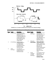
To illustrate the relative magnitude of these
errors in the environmental range, we will take
a worst case situation where all errors are
maximum and additive. A temperature of 45°C
is measured with a type T (copper-constantan)
thermocouple, using the ±2.5 mV range. The
nominal accuracy on this range is 2.5 µV (0.1%
of 2.5 mV), which at 45°C changes the
temperature by 0.06
o
C. The RTD is 25°C but is