


SECTION 12. PROGRAM CONTROL INSTRUCTIONS
12-9
which the alarm call is initiated. The randomized
retry time is divided by the execution interval to
determine how many times Instruction 97 must be
executed before it calls again. The Instruction
must be executed each time the table is.
Parameter 2 specifies which user flag (1-8) is to
be used as the interrupt disable flag. If this flag
is set, Instruction 97 will not initiate an alarm
call. If the CR10 is in the process of trying to
get through with an alarm call, setting the
interrupt disable flag will abort further attempts.
Instruction 97 sets this flag when an alarm call
has received the correct response. Instruction
97 does not clear this flag; the flag will remain
set until cleared by the program or external
command. When the flag is cleared, Instruction
97 is reinitialized.
The RF path and/or telephone number is
entered by following Instruction 97 with one or
more entries of Instruction 63. The RF station
IDs and phone numbers are entered 1 digit at a
time. Decimal equivalents of certain ASCII
characters (Appendix E) are used to identify
breaks. Separate RF stations with a space
(32). Indicate the switch from RF stations to a
telephone number (DC112) with a space (32)
followed by a "T" (84). Carriage Return (13) is
used to end the series of numbers.
If the call is to go through a RF link to a phone,
then the RF Modem is specified in Parameter 1.
See the PC208 and RF manual for additional
interfacing notes.
When the DC112 Modem (Hayes compatible
commands) is specified, the following
commands are sent to the modem before the
phone number: ATV0, ATS7=180, and ATDT.
The first command causes the Modem to
respond with digits rather than words. The
second command causes the modem to wait
for the carrier 180 seconds after calling or
answering. The third command causes the
Modem to dial the number that follows the
command in "Touch Tones". Additional
commands can be entered as part of the
telephone number (e.g., "," for delay or "P" for
pulse dialing). The CR10 will not accept the
line feed found in some Hayes "compatible"
modems.
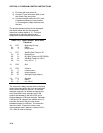
PARAM. DATA
NUMBER TYPE DESCRIPTION
01: 2 Modem option and baud rate
code. Left digit specifies the
modem being used and the
right, the baud rate.
Modem Baud Rate
0 - RF 0 - 300
1 - Short-haul 1 - 1200
2 - DC112 2 - 9600
3 - 76,800
02: 2 Interrupt disable flag
03: 4 Time limit on call, 1 sec.
units
04: 4 Delay between fast retries, 1
sec. units
05: 2 No. of retries at fast rate
06: 4 Delay between slow retries,
1 min. units
07: 4 Input location to store no. of
tries
08: 4 ID to send
*** 98 SEND CHARACTER ***
Instruction 98 is used with Instruction 63 to
send a character or string of characters (up to
15) to the printer. The printer may be either a
addressed or pin-enabled (Section 6.2).
Instruction 63 must immediately follow 98. The
character or characters to send are entered in
Instruction 63 as the decimal equivalents (99 is
the maximum number allowed) of the 7 bit
ASCII character (sent as 8 bits, no parity). For
example, to send the ASCII character control R,
18 would be entered. Enter a null (0) to
terminate the string. Appendix E contains a
listing of the ASCII characters.
If the 9 pin connector is already active when
Instruction 98 is executed, the output request is
put in a queue (see Instruction 96).
This instruction can be used to send a control
character to activate some listing device. The
specified character(s) is sent at the time
Instruction 98 and 63 are executed.
PARAM. DATA
NUMBER TYPE DESCRIPTION